
Exhaust-gas regeneration under rich conditions to improve fuel economy

An air and downstream technology, applied in the direction of exhaust gas recirculation, fuel injection control, adding non-fuel substances to fuel, etc., can solve problems such as ignorance of cooperation

Active Publication Date: 2014-05-07
FORD GLOBAL TECH LLC
View PDF6 Cites 0 Cited by
  • Summary
  • Abstract
  • Description
  • Claims
  • Application Information

AI Technical Summary

Problems solved by technology

However, it does not recognize the synergistic effects of enrichment and exhaust gas recirculation during high load transients

Method used


Image

  • Exhaust-gas regeneration under rich conditions to improve fuel economy
  • Exhaust-gas regeneration under rich conditions to improve fuel economy
  • Exhaust-gas regeneration under rich conditions to improve fuel economy

Examples


Embodiment Construction

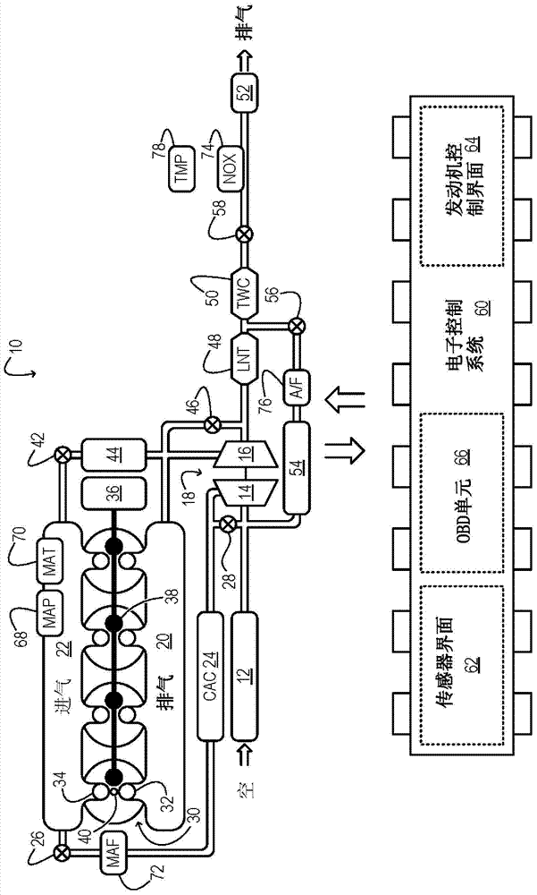
[0020] figure 1 Aspects of an example engine system 10 for a motor vehicle are shown schematically. In engine system 10 , fresh air first enters air cleaner 12 and flows to compressor 14 . The compressor may be any suitable intake compressor, such as a motor driven or drive shaft driven supercharger compressor. In engine system 10 , however, the compressor is mechanically coupled in turbocharger 18 to turbine 16 , which is driven by expanding engine exhaust from exhaust manifold 20 . In one embodiment, the compressor and turbine are coupled in a twin scroll turbocharger. In other embodiments, the turbocharger may be a variable geometry turbocharger (VGT), in which the geometry of the turbine actively changes as engine speed changes.

[0021] Compressor 14 is fluidly coupled to intake manifold 22 via charge air cooling (CAC) 24 and throttle valve 26 . Charge air from the compressor flows through the CAC and throttle valve to the intake manifold. In the illustrated embodime...


PUM


Abstract

A method for operating a boosted gasoline engine. The method includes diluting an intake air charge of the engine to a first level of dilution when operating at a stoichiometric air-to-fuel ratio. The method also includes, in response to a condition of excessive exhaust temperature downstream of the engine, diluting the intake air charge of the engine to a second, greater level of dilution while operating at an enriched air-to-fuel ratio.

Description

technical field [0001] The present invention relates to motor vehicle engineering and, more particularly, to exhaust gas recirculation (EGR). Background technique [0002] Internal combustion engines in vehicles can operate over a wide range of speeds and loads. In a supercharged gasoline engine operating at a stoichiometric air-fuel ratio, high engine loads can lead to undesirably high exhaust gas temperatures. Such temperatures accelerate the aging of materials in engine systems, especially turbo and exhaust aftertreatment components. [0003] One strategy to reduce the exhaust temperature of a gasoline engine during high load transients is to increase the air-fuel mixture. Above stoichiometric ratios, the liquid fuel injected into the engine cylinders does not burn, but instead cools the combustion gases within it by evaporation. Additionally, excess fuel can be transformed endothermicly in the cylinder, providing more cooling. However, this strategy can be detrimenta...

Claims


Application Information

Patent Timeline
Patent Type & Authority Applications(China)
IPC IPC(8): F02M25/07F02D41/00
CPCF02M25/0707F02D23/00F02D41/10F02B29/0406Y02T10/144F02M25/0709F02D21/08F02D41/0007F02D41/1446F02D41/005F02M25/0732F02M25/0718F02M26/05F02M26/06F02M26/15F02M26/24Y02T10/12Y02T10/40
Inventor G·苏尼拉D·J·斯黛奥兹
Owner FORD GLOBAL TECH LLC
Features
  • Generate Ideas
  • Intellectual Property
  • Life Sciences
  • Materials
  • Tech Scout
  • Unparalleled Data Quality
  • Higher Quality Content
  • 60% Fewer Hallucinations
Learn More