Multistage cusped magnetic field plasma thruster segmented ceramic channel

A tangential magnetic field and plasma technology, applied in the field of ion propulsion, can solve the problems of high temperature on the wall surface of the ceramic channel, large plume divergence angle, and low ionization rate, so as to avoid excessive temperature, reduce end surface corrosion, and reduce The effect of oscillation

Active Publication Date: 2014-05-07
HARBIN INST OF TECH
View PDF4 Cites 24 Cited by
  • Summary
  • Abstract
  • Description
  • Claims
  • Application Information

AI Technical Summary

Problems solved by technology

[0005] The present invention aims to solve the problems of plume oscillation in the outlet area of ​​the plasma thruster with a multi-stage tangential magnetic field, large divergence angle of the plu

Method used


Image

  • Multistage cusped magnetic field plasma thruster segmented ceramic channel
  • Multistage cusped magnetic field plasma thruster segmented ceramic channel
  • Multistage cusped magnetic field plasma thruster segmented ceramic channel

Examples


specific Embodiment approach 1

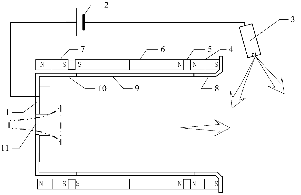
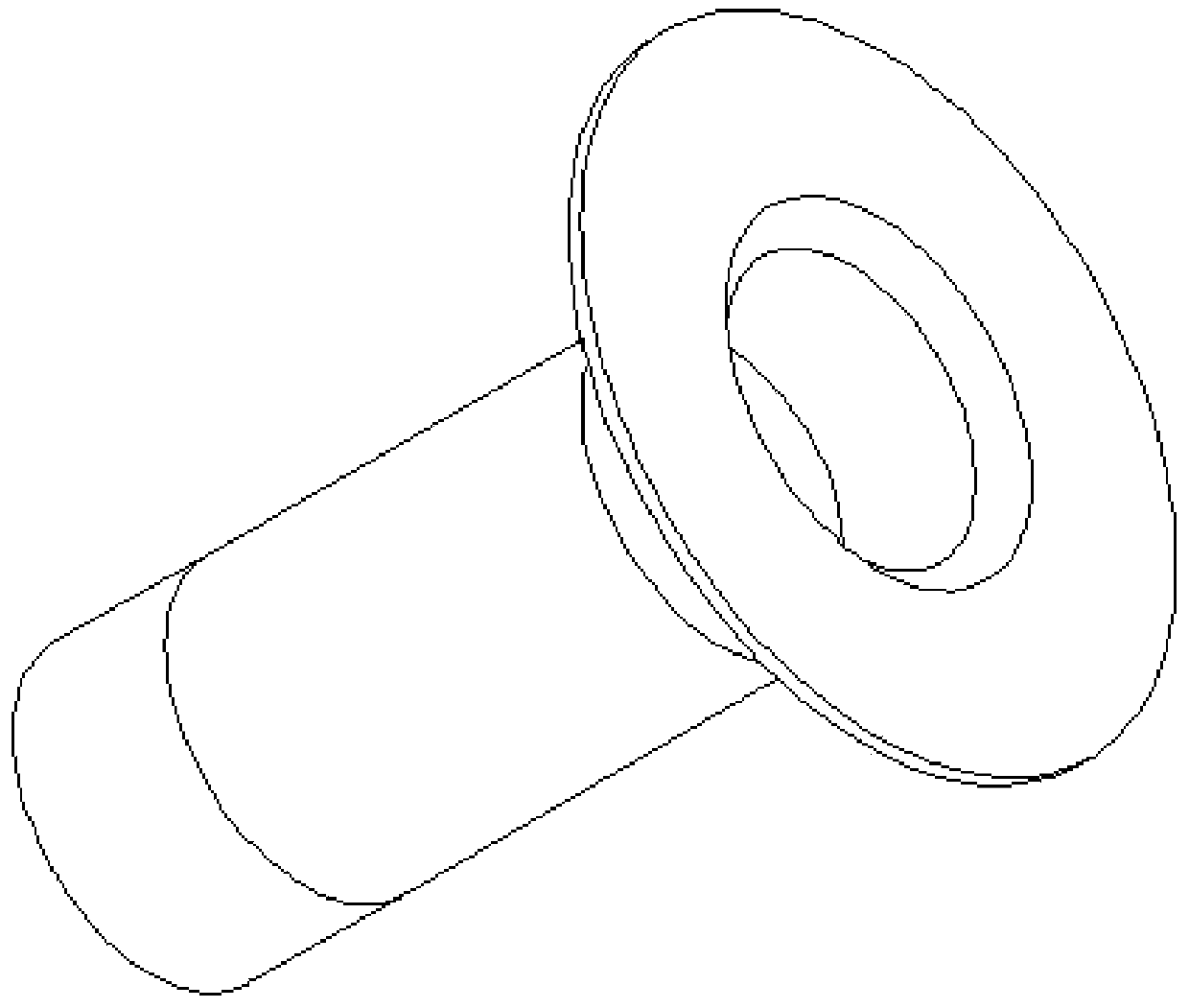
[0021] Specific implementation mode one: the following combination Figure 1 to Figure 4 Describe this embodiment, the segmented ceramic channel of the multi-stage tip tangent magnetic field plasma thruster described in this embodiment, which includes a discharge circuit and a segmented ceramic pipeline;

[0022] The discharge circuit includes an anode 1, a power supply 2 and a hollow cathode 3, the connection terminal of the hollow cathode 3 is connected to the negative terminal of the power supply 2, and the connection terminal of the anode 1 is connected to the positive terminal of the power supply 2;

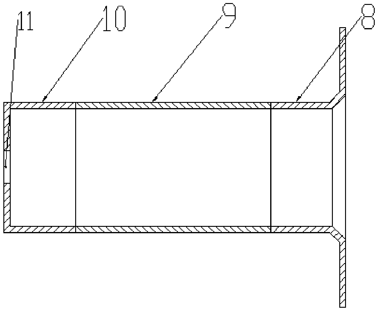
[0023] Segmented ceramic pipes include basic magnetic fields and ceramic channels;

[0024] Described basic magnetic field comprises the first permanent magnet 4, two permeable rings 5, the second permanent magnet 6 and the 3rd permanent magnet 7, passes between the N extreme of the first permanent magnet 4 and the N extreme of the second permanent magnet 6 A magnetic condu...

specific Embodiment approach 2

[0028] Embodiment 2: This embodiment further defines the segmented ceramic channel of the multi-stage tip tangent magnetic field plasma thruster described in Embodiment 1. In this embodiment, the ceramic baffle 8 is made of magnesium oxide material. become.

specific Embodiment approach 3

[0029] Embodiment 3: This embodiment further defines the segmented ceramic channel of the multi-stage pointed tangential magnetic field plasma thruster described in Embodiment 1. In this embodiment, the first ceramic cylinder 9 is boron nitride material.


PUM


Abstract

The invention discloses a multistage cusped magnetic field plasma thruster segmented ceramic channel, relates to the field of plasma thrusting, and aims to solve the problems of plume concussion of an outlet area of a multistage cusped magnetic field plasma thruster, large plume divergence angle, over-high wall temperature of a ceramic channel and low ionization rate. The front section of the ceramic channel is of a baffle structure, so that corrosion of the front end face of the thruster caused by electrons is decreased, the front section of the ceramic channel and an outlet permanent magnet form a magnet loop with a certain shielding function, the magnetic field intensity of the outlet plume area is reduced, the electrons more easily enter the channel to perform ionization, potential drop is concentrated in an outlet magnetic interface, the plume divergence angle is decreased, boron nitride ceramics of a middle section has a low secondary electron emission coefficient, the electron temperature and the ionization rate are high, heat insulation ceramics close to a rear section of an anodic area reduce anodic heat absorbed by the channel, the anodic heat is conducted and dissipated by the aid of an anodic bottom surface, heat dissipation of the permanent magnet is decreased, and demagnetization of the permanent magnet due to high temperature is avoided. The multistage cusped magnetic field plasma thruster segmented ceramic channel is applicable to the field of plasma thrusting.

Description

technical field [0001] The present invention relates to the field of plasma propulsion. Background technique [0002] Electric propulsion has the advantages of high specific impulse, long life, compact structure, small size and light pollution, so it has gradually attracted the attention and favor of the aerospace industry. Among them, the multi-stage pointed cusp magnetic field plasma thruster is a new type of plasma thruster. Multi-stage permanent magnets surround the annular channel, and adjacent magnets are placed with opposite polarities to form a cusp magnetic field, which confines electrons by the magnetic mirror effect. This thruster has the advantages of wide range of thrust and specific impulse, high power density and long life. [0003] However, the magnetic field strength in the exit plume area of ​​this type of thruster is too large, and the local impedance causes an additional potential drop. The ion accelerates in this area and has a large plume divergence an...

Claims


Application Information

Patent Timeline
IPC IPC(8): F03H1/00
Inventor 刘辉孙国顺马成毓陈蓬勃赵隐剑于达仁
Owner HARBIN INST OF TECH
Why Eureka
Try Eureka