Gear system

A gear device and gear technology, which is applied in hoisting devices, transmission parts, portable lifting devices, etc., to achieve the effects of simplifying geometry, reducing power loss, and reducing wear

Inactive Publication Date: 2014-05-07
MIBA SINTER AUSTRIA
View PDF9 Cites 9 Cited by
  • Summary
  • Abstract
  • Description
  • Claims
  • Application Information

AI Technical Summary

Problems solved by technology

Since the tensioning gear is radially displaceable, the split g...

Method used


Image

  • Gear system
  • Gear system
  • Gear system

Examples


Embodiment Construction

[0022] At the outset, it should be pointed out that the same reference symbols or the same component designations are used for the same parts in different embodiments, wherein the disclosure content contained in the entire description can be transferred to the components with the same reference symbols or the same component designations. on the same part. Likewise, selected positions in the description, such as above, below, side, etc., refer to the directly described and illustrated figure and, in the event of a change in position, are sensibly transferred to the new position.

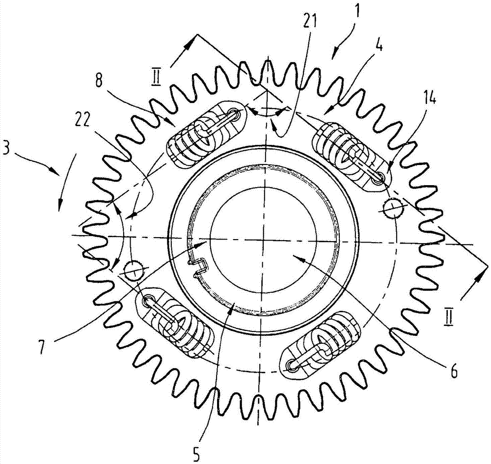
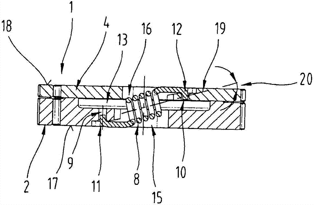
[0023] figure 1 and 2 A gear unit 1 is shown. The gear arrangement 1 , also called split gear, comprises a main gear 2 and a gear 4 , which is rotatable relative to the main gear in a circumferential direction 3 . The main gear 2 can have a hub 5 which can preferably be formed in one piece with the main gear 2 . But it is also possible to arrange the main gear 2 and the rotatable gear 4 directly o...


PUM


Abstract

The invention relates to a gear system (1) comprising a main gear (2) and a gear (4) rotatable relative thereto in circumferential direction (3), comprising spring elements (8), by means of which the rotatable gear (4) is pretensioned in circumferential direction (3) against the main gear (2), wherein the spring elements (8) are connected on the one hand to the main gear (2) and on the other hand to the rotatable gear (4), and wherein the spring elements (8) each have a longitudinal middle axis (19) running obliquely relative to an axial end face (18) of the rotatable gear (4).

Description

technical field [0001] The invention relates to a gear arrangement comprising a main gear and a gear which is rotatable in the circumferential direction relative to the main gear and a plurality of spring elements, by means of which spring elements the rotatable gear is pretensioned in the circumferential direction relative to the main gear, wherein The spring element is connected on one side to the main gear wheel and on the other side to the rotatable gear wheel. In addition, the present invention relates to a gear transmission comprising a first gear and a second gear, wherein the first gear is arranged on a shaft without backlash. Background technique [0002] So-called "split gears" are known from the prior art in various designs. The purpose of this gear structure is to reduce backlash when the gears mesh with each other. [0003] A kind of such A split gear, which includes a main gear and a rotatable gear arranged on the main gear. The two gears are connected to o...

Claims


Application Information

Patent Timeline
IPC IPC(8): F16H55/17
CPCF16H55/18Y10T74/19898F16H57/12F16H2057/126F16H2057/127
Inventor C·桑德纳
Owner MIBA SINTER AUSTRIA
Why Eureka
Try Eureka