
Hybrid cutting tool, chip transporting portion and process for producing a cutting tool

a technology of cutting tools and transporting parts, applied in the direction of manufacturing tools, wrenches, wood boring tools, etc., can solve the problems of complex post-machining, increased complexity of transporting parts, and high cost of cutting tools known to date, and achieves simple and cost-effective process, relatively complex structure, and flexible production.

Inactive Publication Date: 2014-10-30
KENNAMETAL INC
View PDF9 Cites 26 Cited by
  • Summary
  • Abstract
  • Description
  • Claims
  • Application Information

AI Technical Summary

Benefits of technology

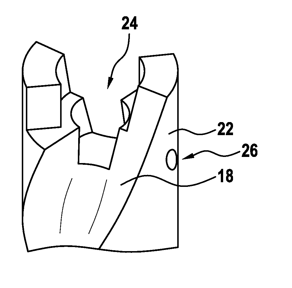
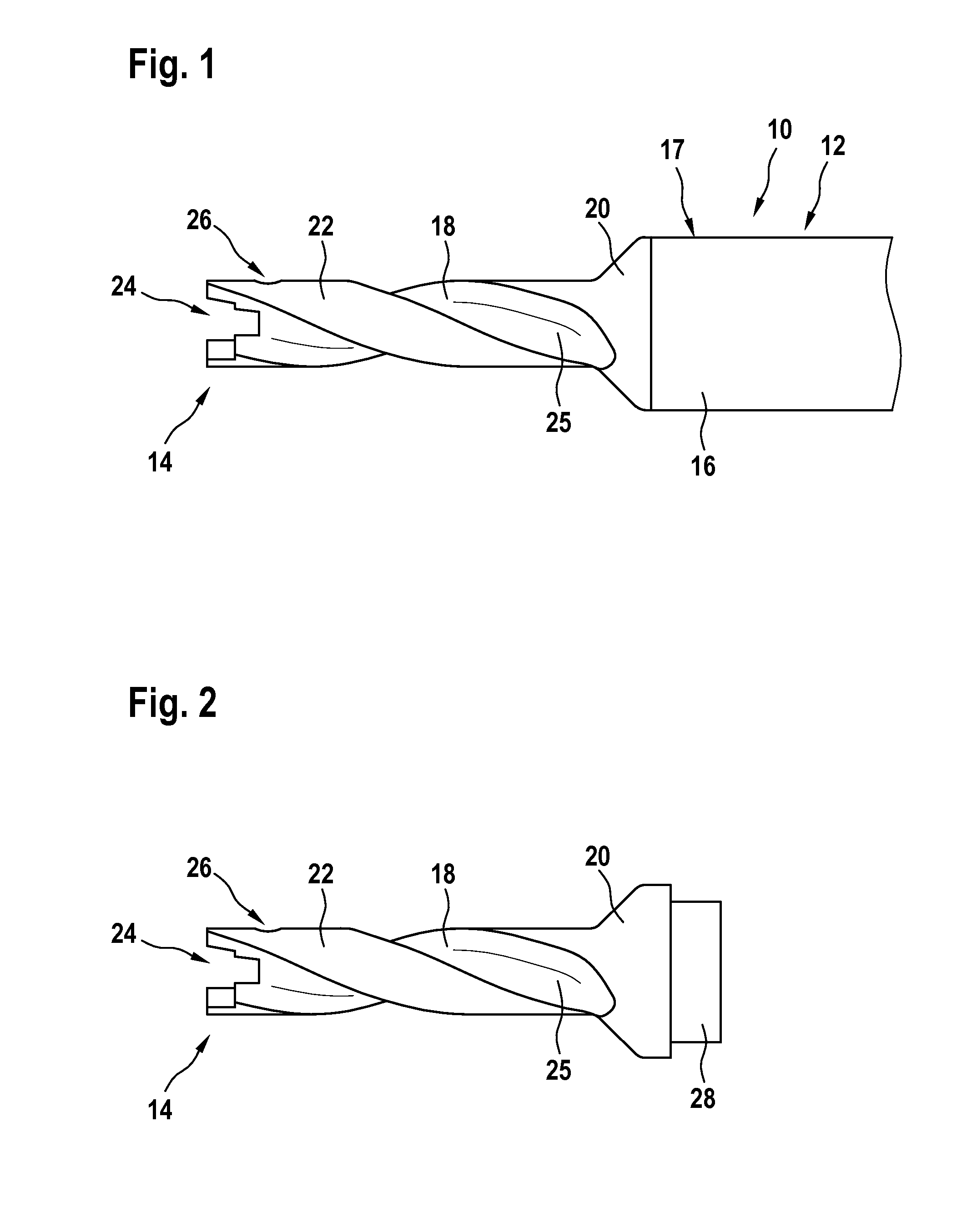
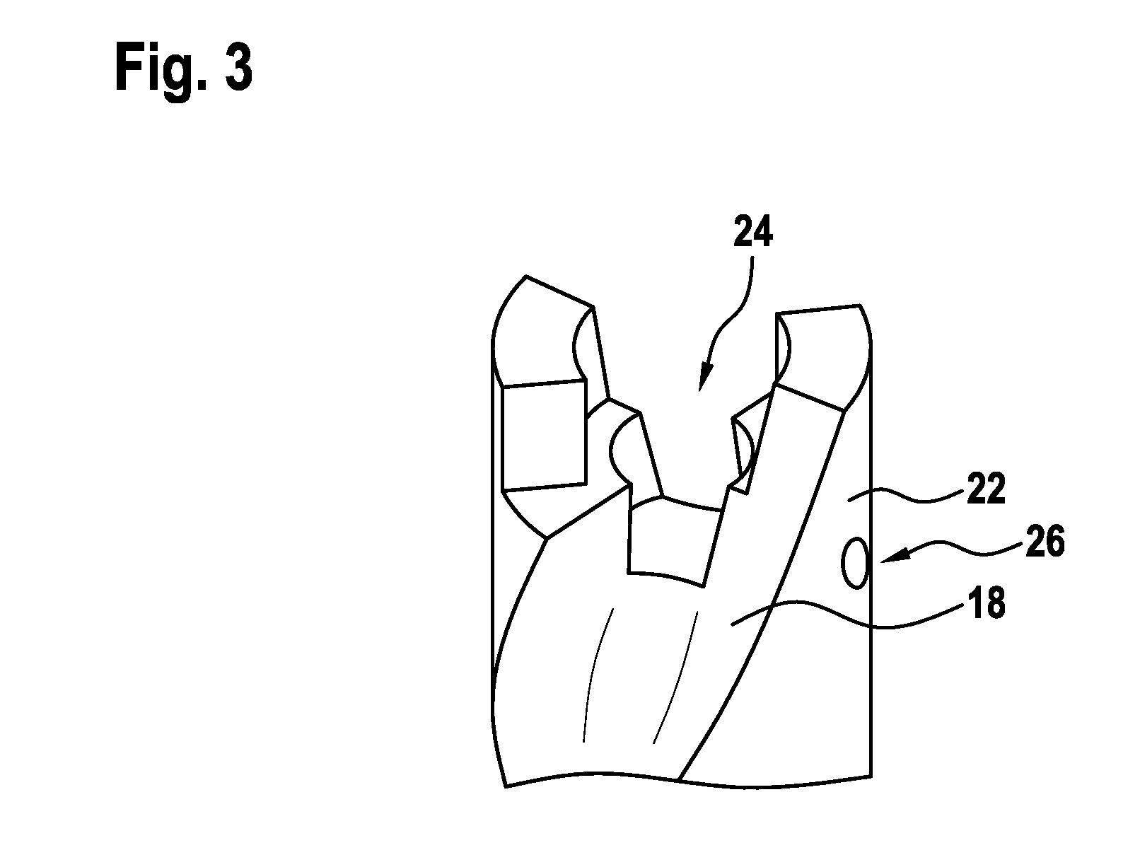
The present invention provides a cutting tool that can be produced flexibly and with relatively complex structures in a simple and cost-effective process. This is achieved by a hybrid composite body, where two differently produced partial regions are fixedly connected to each other. The cutting tool has a chip transporting portion, which is typically the more complex structure, produced by a process from the group of rapid prototyping processes. The shank, which usually does not have a complex geometry, is produced conventionally. This ensures that those parts of the tool which can be provided by a relatively inexpensive process do not also have to be produced by the more complex rapid prototyping process. The chip transporting portion is fixedly connected, in particular soldered, welded or screwed, to the shank, which means that the shank and the chip transporting portion can be produced completely separately, with the chip transporting portion then being fixedly connected to the shank in order to establish a force-fitting connection. This modular concept makes it possible to build up a wide variety of cutting tools by combining different shanks with an extremely wide variety of chip transporting portions.

Problems solved by technology

The chip transporting portions in particular have an increasingly complex structure, and therefore they have to undergo post-machining in complex processes.
It has been found to be disadvantageous that the production of the cutting tools known to date is both complicated and costly.

Method used


Image

  • Hybrid cutting tool, chip transporting portion and process for producing a cutting tool
  • Hybrid cutting tool, chip transporting portion and process for producing a cutting tool
  • Hybrid cutting tool, chip transporting portion and process for producing a cutting tool

Examples


Embodiment Construction

[0033]The foregoing has broadly outlined features and technical advantages of the present disclosure in order that the detailed description of the disclosure that follows may be better understood. Additional features and advantages of the disclosure will be described hereinafter which form the subject of the claims of the disclosure. It should be appreciated by those skilled in the art that the conception and specific embodiments disclosed may be readily utilized as a basis for modifying or designing other structures for carrying out the same purposes of the present disclosure. It should also be realized by those skilled in the art that such equivalent constructions do not depart from the spirit and scope of the disclosure as set forth in the appended claims. The novel features which are believed to be characteristic of the disclosure, both as to its organization and method of operation, together with further objects and advantages will be better understood from the following descri...


PUM

PropertyMeasurementUnit
thicknessaaaaaaaaaa
thicknessaaaaaaaaaa
thicknessaaaaaaaaaa

Abstract

Provision is made of a cutting tool, in particular a drill or a milling cutter, having a shank and a chip transporting portion, which receives a cutting insert, wherein the cutting tool is a hybrid composite body. Furthermore, a chip transporting portion for a cutting tool and also a process for producing a cutting tool are described.

Description

BACKGROUND[0001]1. Field of the Invention[0002]Embodiments of the present invention relate to a cutting tools, chip transporting portions and to processes for producing cutting tools.[0003]2. Background Information[0004]Cutting tools such as drills, milling cutters, turning and piercing tools or reaming tools are known from the prior art. Typically, a cutting tool of this type has a shank, by way of which the cutting tool can be chucked into a machine tool, and also a working portion, which, in the case of a drill, is designed to receive a cutting insert. A cutting tool of this type is usually produced in a milling process, in which case various portions, for example a chip transporting portion of the cutting tool in the case of a drill, can additionally be ground. In an alternative process for producing a cutting tool, it is provided that the cutting tool is produced by means of a sintering process, this process being distinguished by virtue of the fact that it is possible to use m...

Claims


Application Information

Patent Timeline
Patent Type & Authority Applications(United States)
IPC IPC(8): B23B51/02B23B51/06
CPCB23B51/02B23B51/06B23B2228/36B23B2240/00B23B2251/40B23B2251/02B23P15/28B23P15/32B23B2240/16B23B2240/11B23B2231/24Y10T408/89Y10T408/45B23B51/0003B23B27/16B23B27/18B23C5/18B23C5/20B23D43/04B26F1/14B23B51/0004B23B51/0002
Inventor GEY, CHRISTOPH
Owner KENNAMETAL INC
Learn More