
Crystal-growing furnace with heating improvement structure

a technology of heating improvement and crystal growth furnace, which is applied in the direction of crystal growth process, crystal growth process, chemistry apparatus and processes, etc., can solve the problems of saving manufacturing cost, and achieve the effect of saving energy, saving energy and time consumption, and improving efficiency in melting silicon materials

Inactive Publication Date: 2009-07-30
GREEN ENERGY TECH
View PDF5 Cites 21 Cited by
  • Summary
  • Abstract
  • Description
  • Claims
  • Application Information

AI Technical Summary

Benefits of technology

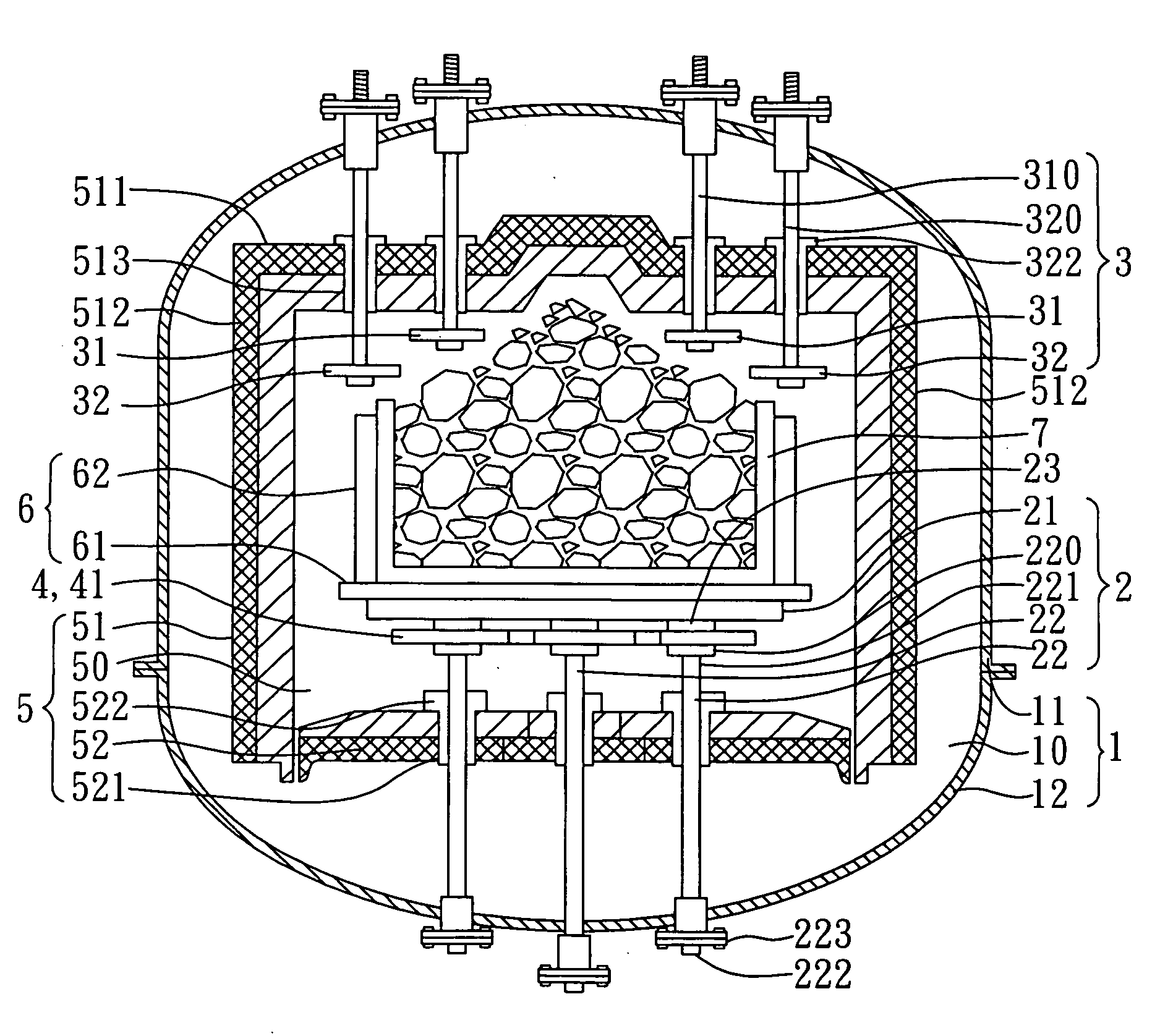
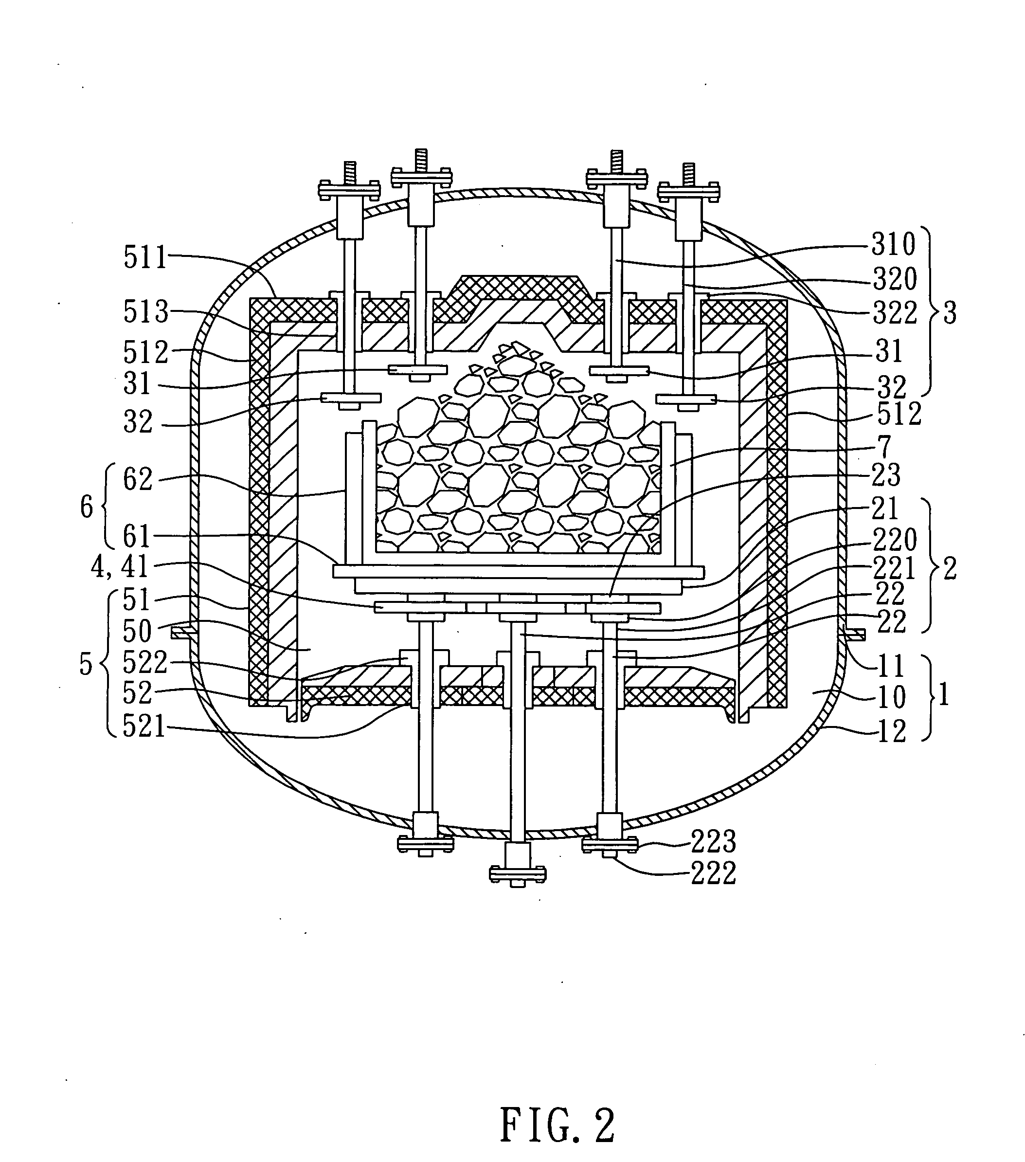
[0009]The crucible is heated simultaneously at the top and bottom thereof by the top and bottom heaters, respectively, so as to enhance efficiency in melting the silicon material in the crucible. Besides, according to the present invention, the first level heater and the second level heater of the top heater are arrayed and arranged in conformity with the silicon material which is stacked and formed as a pyramid-like shape, such that the first level heater and the second level heater get closer to the silicon material and help the silicon material absorb energy at an initiative stage. When the silicon material around the periphery of the pyramid-like shape is melted, molten silicon slurry will flow directly into the spacing among particles of the silicon material. This will expedite internal part of the silicon material to absorb energy. As a result, a desirable cycle will be established to expedite melting the whole silicon material in the crucible so as to save energy and time consumption.
[0010]Further, since both of the top and the bottom heaters are simple in geometric configuration, and since the heaters are symmetrical with one another, the crucible can be heated uniformly. This not only saves energy and makes the heating job convenient, but also saves cost in manufacture.
[0011]The crystal-growing furnace comprises a heating room arranged inside the furnace chamber of the furnace body, and is formed inside of the heating room with an inner space which accommodates, at least, the table plate of the supporting table, the top heater, and the bottom heater. Besides, the heating room has a double-layer structure, including an internal insulating layer and an external warm-keeping layer, such that the internal insulating layer serves to prevent heat from leaking out of the heating room, while the external warm-keeping layer can enhance warm-keeping effectiveness so as to achieve the purpose of energy saving.
[0014]The second level heater of the top heater includes a surrounding resistor and two graphite electrodes, where the two graphite electrodes are connected, respectively, with the surrounding resistor so as to provide electrical power to the second level heater for heating purpose. The bottom heater includes a plurality of bending resistor strips disposed, respectively, underneath the table plate of the supporting table. Each of the supporting posts includes a graphite electrode post for supporting underneath one of the resistor strips and for electrically connecting therewith. There are a plurality of insulating sheets interposed between the table plate of the supporting table and the plural bending resistor strips. Further, each of the supporting posts has an adjusting nut. The graphite electrode posts are each provided, at its top, with an external thread so that the adjusting nuts can be engaged with the external threads and thus support against the bending resistor strips. This will not only enlarge electrical contacting area, but also enhance stability in supporting the table plate. The adjusting nut is made of graphite.

Problems solved by technology

This not only saves energy and makes the heating job convenient, but also saves cost in manufacture.

Method used


Image

  • Crystal-growing furnace with heating improvement structure
  • Crystal-growing furnace with heating improvement structure
  • Crystal-growing furnace with heating improvement structure

Examples


Embodiment Construction

[0021]Referring to FIG. 2, a cross-sectional view illustrating a crystal-growing furnace, the crystal-growing furnace comprises a furnace body 1, a supporting table 2, a top heater 3, and a bottom heater 4.

[0022]The furnace body 1 includes an upper body 11 and a lower body 12, wherein the lower body 12 is attached to underneath of the upper body 11 so as to form together an enclosed furnace chamber 10. The supporting table 2 includes a table plate 21 and eight supporting posts 22, wherein the table plate 21 is supported by and fixed to the lower body 12 of the crystal-growing furnace by the supporting posts 22.

[0023]As shown in FIG. 2, a heating room 5 is arranged inside the furnace chamber 10 of the furnace body 1, and includes an upper cover 51 and a lower partition 52. The upper cover 51 is fixed to inside of the upper body 11, and the lower partition 52 fixed to inside of the lower body 12, such that the upper cover 51 is covered on the lower partition 52 so as to enclose and fo...


PUM


Abstract

A crystal-growing furnace with a heating improvement structure includes a furnace body, a supporting table, a top heater, and a bottom heater. When the silicon material around the top heater is melted, molten silicon slurry will flow directly into the spacing among particles of the silicon material. This will expedite internal part of the silicon material to absorb energy. As a result, a desirable cycle will be established to expedite melting the whole silicon material in the crucible. The crucible is heated at the bottom thereof by the bottom heater directly so as to enhance efficiency in melting the silicon material in the crucible, and to save energy and time consumed by the crystal-growing furnace. Further, since both of the top and the bottom heaters are symmetrical with one another, the crucible can be heated uniformly. This not only saves energy and makes the heating job convenient, but also saves cost in manufacture.

Description

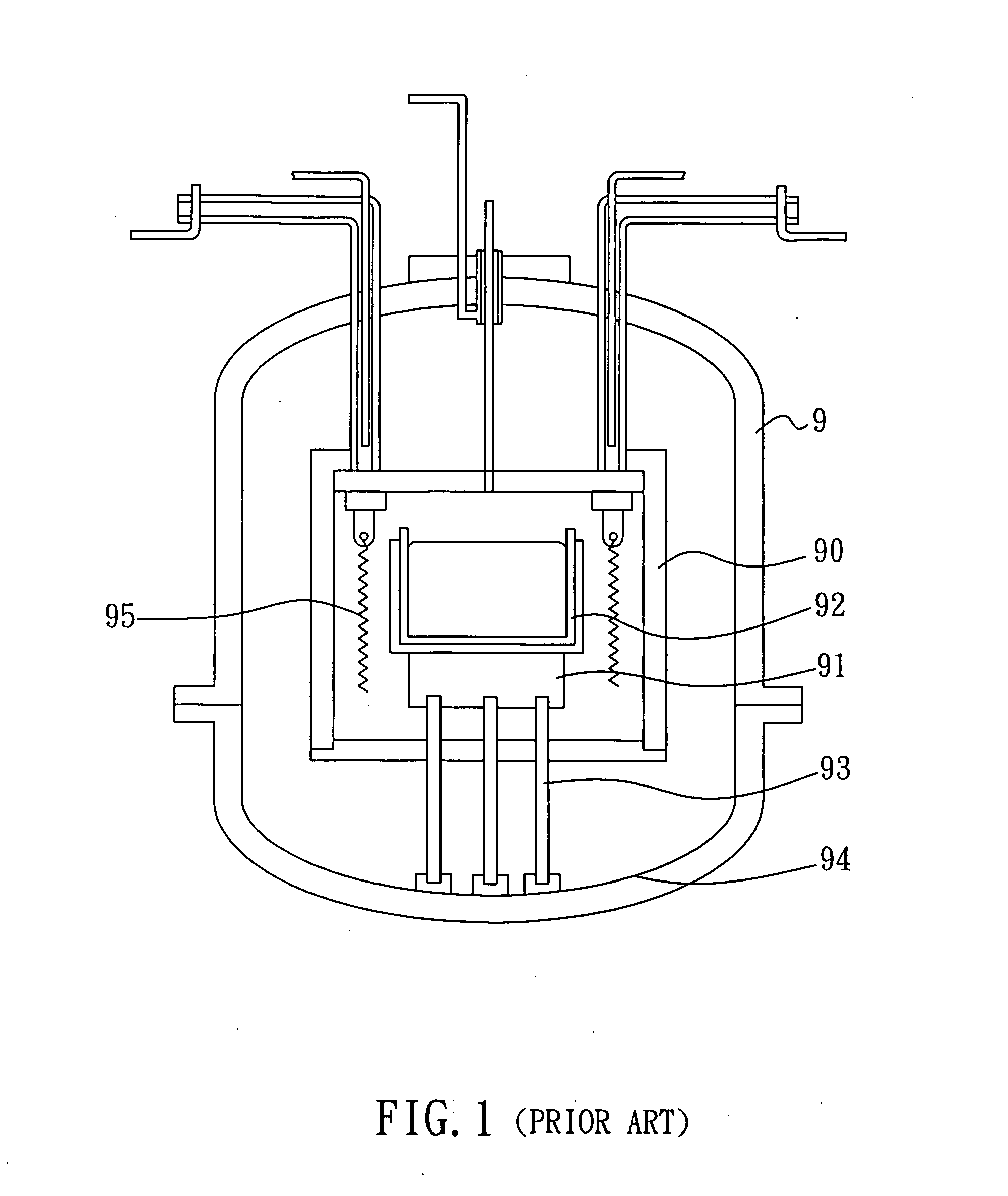
BACKGROUND OF THE INVENTION[0001]1. Field of the Invention[0002]The present invention relates to a furnace for growing multiple crystals of silicon, more particularly, to a crystal-growing furnace with a heating improvement structure.[0003]2. Description of Related Art[0004]Referring to FIG. 1, a schematic view illustrating a conventional crystal-growing furnace, a heating room 90 is provided inside the furnace 9 where a table plate 91 and a crucible 92 are arranged inside the heating room 90, wherein the crucible 92 contains molten silicon slurry. Three supporting posts 93 are fixed to a lower body 94 of the crystal-growing furnace 9, and are supportively arranged underneath the table plate 91 and the crucible 92.[0005]As shown in FIG. 1, heaters 95 are arranged around the crucible 92 so as to heat the silicon slurry through radiant heat Nevertheless, the top and the bottom of the crucible 92 cannot be heated and uniformly. Besides, in order to provide the crucible 92 a firm and st...

Claims


Application Information

Patent Timeline
IPC IPC(8): C30B35/00
CPCC30B11/002C30B11/003C30B28/06C30B29/06Y10T117/1024
Inventor LEW, SHIOW-JENGLIN, HUR-LON
Owner GREEN ENERGY TECH
Learn More