
Condensation pipeline vibration damper and vibration damping method

A technology for condensing pipes and shock absorbers, which is applied in the directions of pipe elements, pipes/pipe joints/pipe fittings, mechanical equipment, etc., can solve the problems of installation and construction difficulties, influence attenuation effect, parameter selection difficulties, etc., and achieve convenient installation and disassembly. , Improve the utilization efficiency and enhance the effect of heat transfer

Active Publication Date: 2016-08-03
CHINA PETROLEUM & CHEM CORP +2
View PDF6 Cites 0 Cited by
  • Summary
  • Abstract
  • Description
  • Claims
  • Application Information

AI Technical Summary

Problems solved by technology

[0006] 1) The volume of the shock absorber is large; such as buffer tanks, accumulators, etc., the large volume not only brings great difficulties to installation and construction, but also occupies a large installation space
[0007] 2) There is no easy way to adjust the resonance frequency of the shock absorber to ensure its damping effect of fluid pulsation
Because of changes in working conditions, it is possible to change the fluid pulsation frequency, thereby affecting the attenuation effect
[0008] 3) It is difficult to select parameters. For example, for buffer tanks and accumulators, the most important thing is the working volume and pre-charge pressure. The determination of these parameters often needs to be determined through repeated experiments, which is difficult to popularize and apply
[0009] 4) The attenuation performance is low, and the attenuation effect is not ideal
[0010] According to relevant literature and reports at home and abroad, there are relatively many shock absorbers developed for gas pipeline vibration and liquid pipeline vibration, but for pipeline vibration with phase change, no relevant shock absorbers have been reported.

Method used


Image

  • Condensation pipeline vibration damper and vibration damping method
  • Condensation pipeline vibration damper and vibration damping method
  • Condensation pipeline vibration damper and vibration damping method

Examples


Embodiment Construction

[0039] Specific embodiments of the present invention will be further described in detail below in conjunction with the accompanying drawings.

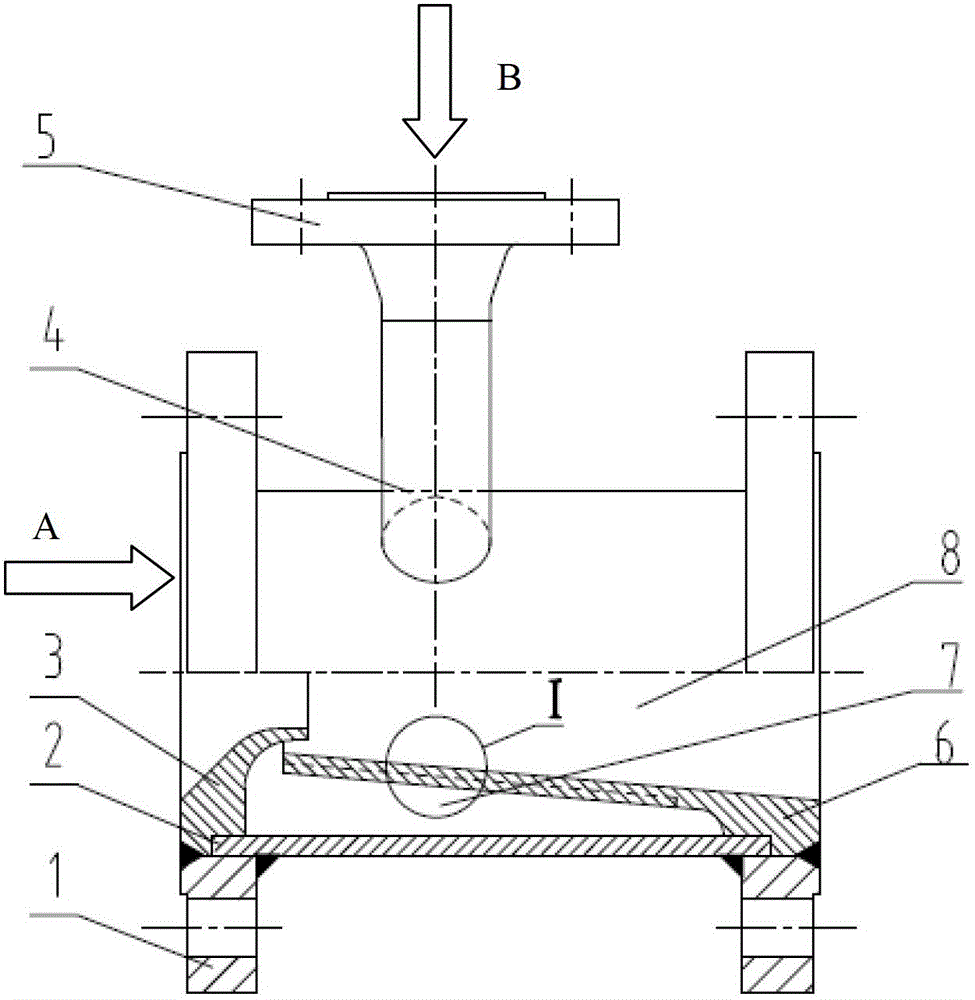
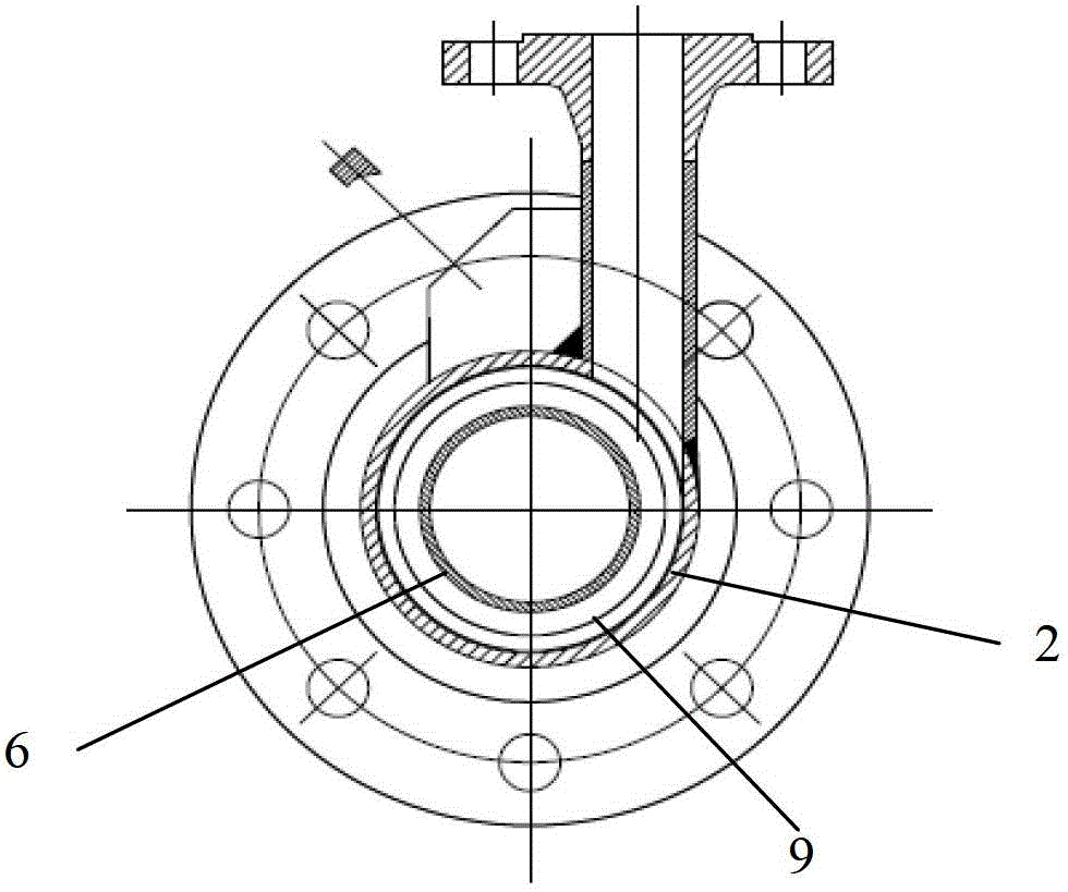
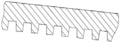
[0040] Such as figure 1 As shown, a condensate pipeline shock absorber includes a main liquid inlet, and the main liquid inlet communicates with a branch pipe 4 for two-phase flow; the shock absorber includes an inner chamber 8 that communicates with the main liquid inlet. , and the outer cavity 7 communicated with the branch pipe 4, the inner cavity 8 is sleeved in the outer cavity 7, and the inner cavity 8 is provided with a gap at the communication part with the outer cavity 7; the inner wall of the outer cavity 7 A threaded groove 9 is provided. The entrance of the inner chamber 8 is a tapered mouth structure, and the diameter of the inner chamber 8 at the communication point with the outer chamber 7 is smaller than that at the entrance of the inner chamber 8 . The outer edge of the inner cavity 8 is the inner cylinder 6, the out...


PUM


Abstract

The invention discloses a shock absorber of a condensation pipeline. The shock absorber of the condensation pipeline comprises a main liquid flow inlet, wherein the main liquid flow inlet is communicated with a branch pipe through which a two-phase flow passes, and the branch pipe is perpendicular to the direction of the main liquid flow inlet. The shock absorber of the condensation pipeline comprises an inner cavity and an outer cavity, wherein the inner cavity is communicated with the main liquid flow inlet, the outer cavity is communicated with the branch pipe, the inner cavity is sleeved with the outer cavity, the position, communicated with the outer cavity, of the inner cavity is provided with a gap, and the inner wall of the outer cavity is provided with a threaded groove structure. The threaded groove structure is utilized for enhancing heat transferring and accelerating condensation, and therefore pressure pulsation caused by vapor condensation is reduced to be the minimum; condensed fluid flows back into the inner cavity, original pressure fluctuation is changed again when the condensed fluid passes through a tapered opening, and dual shock absorption is achieved. The shock absorber can be applicable to the condensation pipeline where gas and liquid exist at the same time, and the shock absorption effect is good.

Description

technical field [0001] The invention relates to the field of pipeline vibration reduction, in particular to a condensation pipeline vibration damper. Background technique [0002] Pipelines are widely used in production equipment in petroleum, chemical, power station and other industries. Under the action of a certain pressure and velocity of the fluid, hydrodynamic pressure will be generated on the walls of these pipes. The unsteady pipe flow will cause the vibration of the pipe. For example, due to the intermittent suction and displacement of the reciprocating pump and the closing of the valve, the parameters such as the pressure, velocity, and density of the pipe flow will change periodically with time and position. The resulting phenomenon is called "pipe flow pulsation". Pipe flow pulsation is the main cause of pipeline vibration. This pulsation is divided into air flow and liquid flow, which vary according to the transport medium. Whether it is air flow or liquid f...

Claims


Application Information

Patent Timeline
Patent Type & Authority Patents(China)
IPC IPC(8): F16L55/04
CPCF16L55/041F16L55/05
Inventor 王学生刘勇陈琴珠陈国康窦伟圻黄勇辉
Owner CHINA PETROLEUM & CHEM CORP
Learn More