Light-emitting diode (LED) curve-face light guide lamp

A technology of LED light bar and light guide lamp, which is applied in the direction of optics, light guide, light source, etc., can solve the problems of not being able to illuminate the surroundings uniformly, discomfort of the user's eyes, and high production cost, and achieve easy popularization and use, soft light, and low production cost. Reduced effect

Inactive Publication Date: 2014-05-07
王金志
View PDF4 Cites 4 Cited by
  • Summary
  • Abstract
  • Description
  • Claims
  • Application Information

AI Technical Summary

Problems solved by technology

[0002] LED lamps are more and more popular due to energy saving. There are various LED lamps on the market, but they are basically a dot matrix light source composed of many LED lamp beads. The lighting source is directly generated by each LED lamp bead. Point light source, the area of ​​each local point light source is very small and very bright, so it is very dazzling and brings discomfort to the user's eyes, and this kind of light tube needs a large number of LED lamp beads to be installed on the light board to achieve the required brightness. The production cost is high; there is also a kind of LED flat panel lamp on the market, which is a kind of lamp in which a luminous body is arranged on the side of the flat panel, and the light is scattered into a surface light source through the light guide point on the flat tube plate.
The light irradiated by this flat panel light is uniform and soft, but because this kind of flat panel light guides light through the flat panel, it is generally a small flat panel light, which is used as a decorative light. The flat panel light used as general lighting is not only inconvenient to install because of its large expansion area, Moreover, the flat panel can only illuminate the irradiation area in front of the flat panel, and the light on the side is weak, and cannot evenly illuminate the surrounding like a fluorescent tube, so the actual use is very limited; as for the LED curved surface light guide lamp, no such products have been found yet.

Method used


Image

  • Light-emitting diode (LED) curve-face light guide lamp
  • Light-emitting diode (LED) curve-face light guide lamp
  • Light-emitting diode (LED) curve-face light guide lamp

Examples


Embodiment Construction

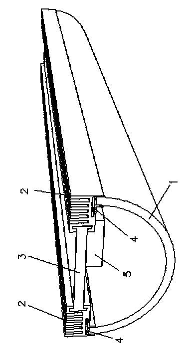
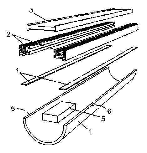
[0021] Such as Figure 1 to Figure 3 As shown, the present invention includes: a curved light guide plate 1, an LED light bar 4, and a heat dissipation bar 2. LED light bar 4, the light-emitting surface of the LED faces the cross-section, and is in contact with the longitudinal section. The LED is connected to the aluminum substrate. Contacting and connecting with the heat sink; said longitudinal section 6 means that the extended surface of the section passes through the axis line of the curved light guide plate, and coincides with the axis line, and the inner wall surface of the curved light guide plate is provided with reflective points and reflective layers 9, A light-scattering layer 8 is provided on the outer wall surface of the curved light guide plate, and the reflective layer and the light-scattering layer are in contact with the curved light guide plate. The curved light guide plate is a transparent tube with smooth inner and outer walls. The reflective layer 9 and ...


PUM


Abstract

The invention relates to a light-emitting diode (LED) curve-face light guide lamp which comprises a curve-face light guide plate, an LED lamp strip and a radiating strip. The section of the curve-face light guide plate is a part of a ring, the LED lamp strip is arranged on the vertical section of the curve-face light guide plate, the light-emitting face of the LED faces the section and is in contact connection with the vertical section, the back of the LED is connected with an aluminum substrate lamp strip to form the LED lamp strip, the LED lamp strip is inserted into an aluminum substrate connection groove of a radiating fin, and an aluminum substrate of the lamp strip is in contact connection with the radiating fin. Lighting is conducted through scattering of light reflection points of the whole curve-face light guide plate, the light-emitting area is large, and the light is even. The curve-face light guide plate is arc, so that the lamp saves space obviously compared with a flat light guide lamp with identical area.

Description

technical field [0001] The invention relates to an LED lamp, in particular to an LED curved surface light guide lamp. Background technique [0002] LED lamps are more and more popular due to energy saving. There are various LED lamps on the market, but they are basically a dot matrix light source composed of many LED lamp beads. The lighting source is directly generated by each LED lamp bead. Point light source, the area of ​​each local point light source is very small and very bright, so it is very dazzling and brings discomfort to the user's eyes, and this kind of light tube needs a large number of LED lamp beads to be installed on the light board to achieve the required brightness. The production cost is high; there is also a kind of LED flat panel lamp on the market, which is a kind of lamp in which a luminous body is arranged on the side of the flat panel, and the light is scattered into a surface light source through the light guide point on the flat duct plate. The l...

Claims


Application Information

Patent Timeline
Patent Type & Authority Applications(China)
IPC IPC(8): F21S2/00F21V8/00F21Y101/02F21K9/00F21Y115/10
Inventor 王金志王波
Owner 王金志
Why Eureka
Try Eureka