Efficient burner outer fire cover

A technology of outer fire cover and burner, which is applied in the direction of burner, gas fuel burner, combustion method, etc. It can solve the problems of flameout and flameout, achieve stable flame combustion, improve thermal efficiency, and prevent cross-burning

Inactive Publication Date: 2014-05-07
周崇高
View PDF5 Cites 2 Cited by
  • Summary
  • Abstract
  • Description
  • Claims
  • Application Information

AI Technical Summary

Problems solved by technology

[0002] The structure of the burner in the existing gas cooker generally includes a fire cover seat, a central fire cover and an outer fire cover. The fire cover seat is respectively provided with a central fire chamber and an outer fire chamber. On the central fire chamber and the outer fire chamber, the bottom of the central fire cover is provided with a central fire cover cavity that communicates with the central fire chamber, and a plurality of fire injection holes are opened on the outer wall of the central fire cover. The outer fire cover is The annular fire cover, the annular fire cover is composed of an annular top wall, an annular inner wall and an annular outer side wall. The bottom of the annular fire cover is formed with an annular through groove, and several main fires are opened on the annular outer wall of the annular fire cover along its circumferential direction. hole, because the main fire in the traditional outer fire cover is closer to the center fire, and the fire outlet hole of the inner main fire is set at the middle and lower part of the fire cover. Insufficient secondary air replenishment, easy to cause misfire, flameout, etc.

Method used


Image

  • Efficient burner outer fire cover
  • Efficient burner outer fire cover
  • Efficient burner outer fire cover

Examples


Embodiment Construction

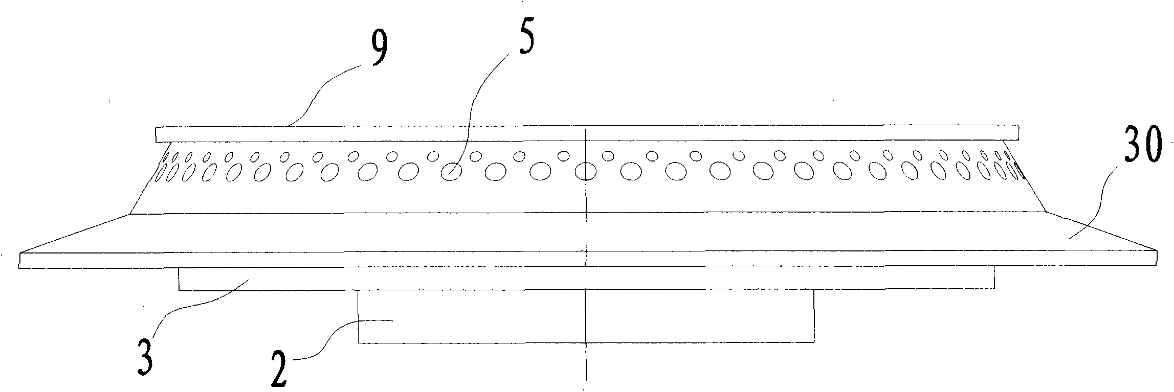
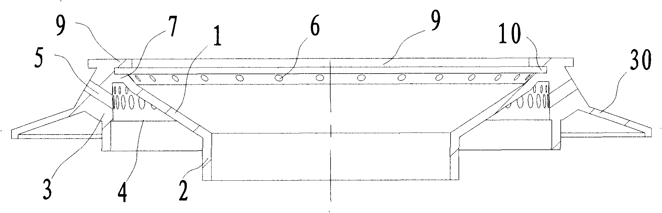
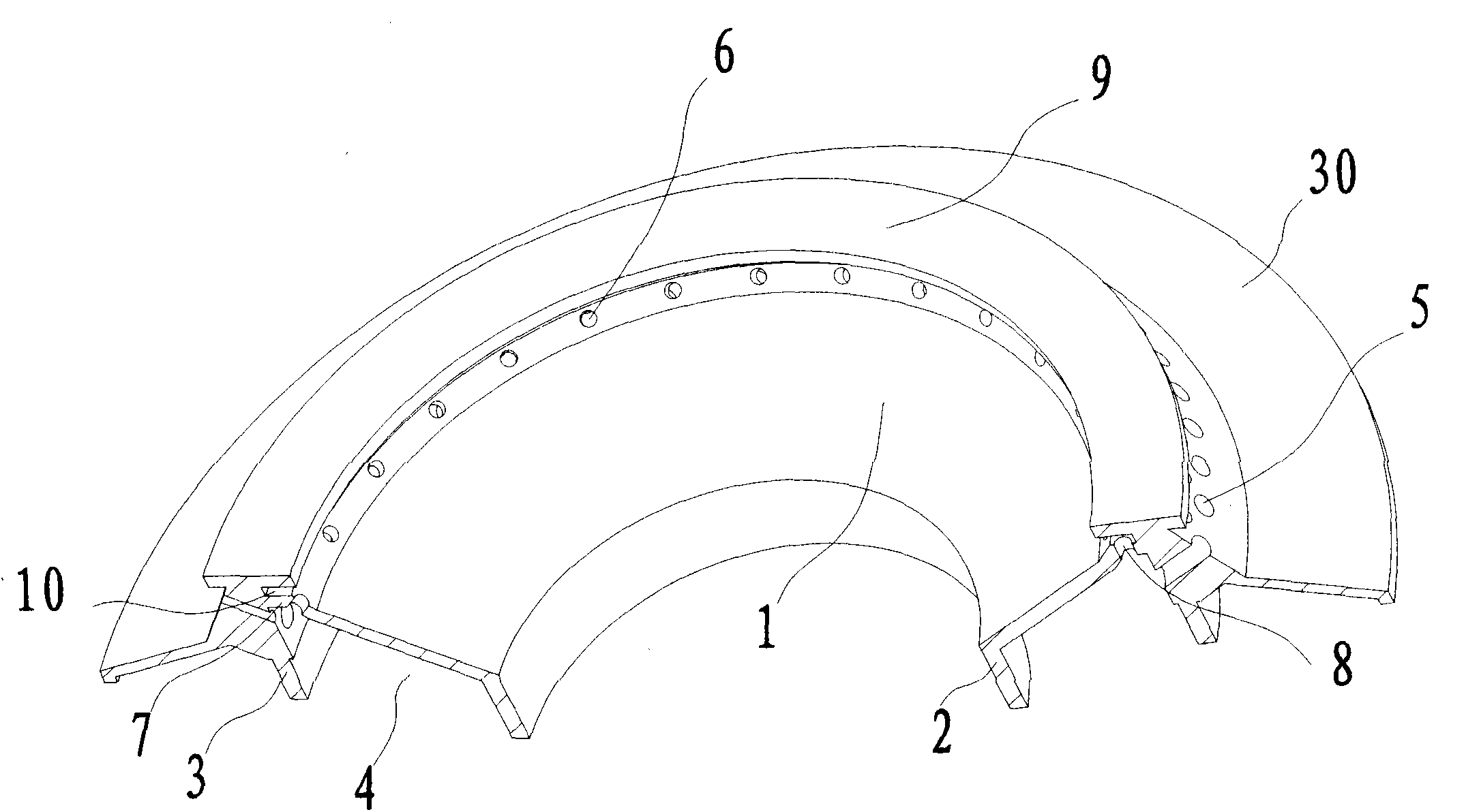
[0016] High-efficiency burner outer fire cover, such as Figure 1 to Figure 4 As shown, the outer fire cover is an annular fire cover, and the outer fire cover is composed of an annular top wall 1, an annular inner side wall 2 and an annular outer side wall 3, the annular inner side wall 2 and the annular outer side wall 3 are vertically arranged, and the annular top wall 1 Relative to the annular inner sidewall 2 and the annular outer sidewall 3, which are gradually raised from the inside to the outside, the annular top wall 1, the annular inner sidewall 2 and the annular outer sidewall 3 form an annular gas mixing groove 4; on the annular outer sidewall 3 There are several main fire holes 5 respectively communicated with the annular air mixing groove 4 along its circumferential direction; the top of the annular top wall 1 is provided with several oblique fire holes 6 respectively communicated with the annular air mixing groove 4 along its circumferential direction; A horizon...


PUM


Abstract

The invention discloses an efficient burner outer fire cover. The outer fire cover is an annular fire cover and is formed by an annular top wall, an annular inside wall and an annular outside wall, which form an annular gas mixing slot; a plurality of main fire holes respectively communicated with the annular gas mixing slot are formed in the annular outside wall; a horizontal connection part is formed at the connection part between the annular top wall and the annular outside wall; a plurality of fuel gas through holes communicated with the annular gas mixing slot are formed in the horizontal connection part; a horizontally arranged annular top cover is further connected to the top end of the annular outside wall; an annular flame slot provided with an inward opening and communicated with the multiple fuel gas through holes is formed between the lower surface of the annular top cover and the upper surface of the horizontal connection part; when a pot is placed during use, annular central fire is away from the central fire, crossing burning difficultly occurs during burning, the pot is not separated from the fire and the flame, three contact areas, namely a central fire area, an annular middle flame area and an outer main fire area, exist between a pot bottom and the flame, three levels of uniform heating effects for the pot bottom are realized, the heat efficiency is improved, and the flame burning is more stable.

Description

【Technical field】 [0001] The invention belongs to a burner, in particular to an outer fire cover of a high-efficiency burner. 【Background technique】 [0002] The structure of the burner in the existing gas cooker generally includes a fire cover seat, a central fire cover and an outer fire cover. The fire cover seat is respectively provided with a central fire chamber and an outer fire chamber. On the central fire chamber and the outer fire chamber, the bottom of the central fire cover is provided with a central fire cover cavity that communicates with the central fire chamber, and a plurality of fire injection holes are opened on the outer wall of the central fire cover. The outer fire cover is The annular fire cover, the annular fire cover is composed of an annular top wall, an annular inner wall and an annular outer side wall. The bottom of the annular fire cover is formed with an annular through groove, and several main fires are opened on the annular outer wall of the an...

Claims


Application Information

Patent Timeline
IPC IPC(8): F23D14/46
Inventor 周崇高
Owner 周崇高
Why Eureka
Try Eureka