
Off-axis alignment system and alignment method

An alignment system and off-axis technology, applied in the off-axis alignment system and the field of alignment, can solve the problems of large defocusing effect, high requirements for coherence of illumination beams, and difficult implementation, etc., and achieves simple optical path structure, Eliminates spatial coherence requirements, small size effect

Active Publication Date: 2014-05-07
SHANGHAI MICRO ELECTRONICS EQUIP (GRP) CO LTD
View PDF6 Cites 32 Cited by
  • Summary
  • Abstract
  • Description
  • Claims
  • Application Information

AI Technical Summary

Problems solved by technology

[0006] The purpose of the present invention is to provide an off-axis alignment system and alignment method to solve the problem that the alignment mark tilt and defocus have a great influence on the detection results in the existing off-axis alignment system, and the requirements for the coherence of the illumination beam are relatively high. high or require the use of complex components such as wedge arrays, making implementation difficult

Method used


Image

  • Off-axis alignment system and alignment method
  • Off-axis alignment system and alignment method
  • Off-axis alignment system and alignment method

Examples


Embodiment 1

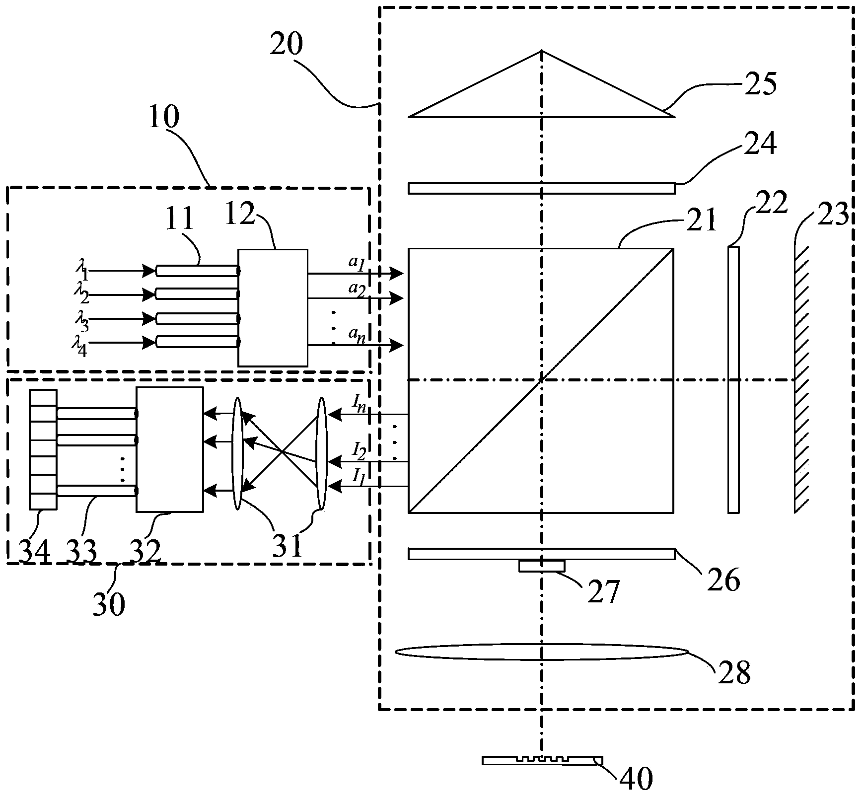
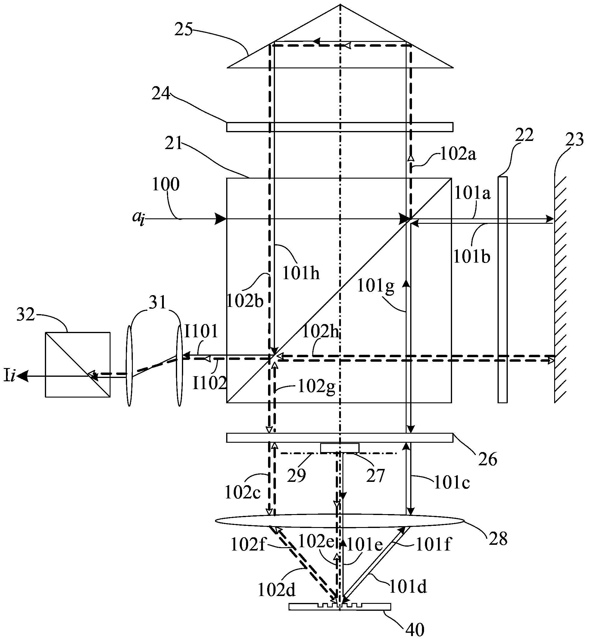
[0041] The off-axis alignment system provided by the present invention, such as figure 1 As shown, according to the beam propagation path, it includes an illumination module 10, an interference module 20, and a detection module 30. The illumination module 10 and the detection module 30 are located on the same side of the interference module 20. The illumination module 10 includes a light source (in the figure) (Not shown), the multi-wavelength incident fiber 11 and the beam splitting element 12. Preferably, the light source is a laser, because the laser has high brightness and good directivity. In the first embodiment, the light source is a single-frequency laser, which emits illumination The light beam is linearly polarized light with a single frequency. Preferably, the illumination module 10 further includes a shutter (not shown in the figure), an optical isolator (not shown in the figure) and a phase modulator (not shown in the figure) The shutter is used to block the illumin...

Embodiment 2

[0080] The difference between this embodiment and Embodiment 1 is that the light source adopts a dual-frequency laser, and the beam splitter 52 is a laser frequency splitter. Preferably, the laser frequency splitter is an electro-optic modulator or an acousto-optic modulator.

[0081] The off-axis alignment system provided by the present invention, such as Figure 13 As shown, it includes an illumination module 50, an interference module 60, and a detection module 70. The illumination module 50 and the detection module 70 are located on the same side of the interference module 60. The illumination module 50 includes a light source (not shown in the figure), The multi-wavelength incident fiber 51 and the beam splitter 52. In the second embodiment, the light source is a dual-frequency laser, and the beam splitter 52 is a laser frequency splitter. Specifically, the laser frequency splitter is an electro-optic modulator or an acousto-optic modulator. The interference module 60 include...


PUM


Abstract

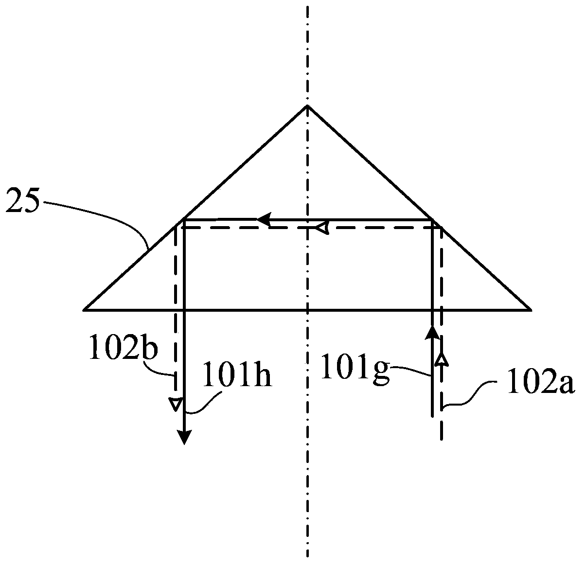
The present invention relates to an off-axis alignment system and a method thereof. The off-axis alignment system comprises an illumination module, an interference module and a detection module, wherein the illumination module comprises a light source, multi-wavelength incidence optical fibers and a light splitting element, the interference module comprises a polarization beam splitter, the one polarization beam splitter side relative to the one side of the illumination module and the detection module is provided with a first 1 / 4 wave plate and a first reflecting mirror, the other two sides of the polarization beam splitter are respectively provided with a second 1 / 4 wave plate and a cube-corner prism, and a third 1 / 4 wave plate, a second reflecting mirror and a lens, the second reflecting mirror is positioned on the rear focal plane of the lens, the center of the bottom surface of the cube-corner prism is positioned on the optical axis of the lens, and the detection module comprises a detection lens set, a polarization device, detection optical fibers and a photoelectric detector. According to the present invention, the grating double-diffraction technology of the off-axis alignment system is adopted, the incidence light beam passes through the alignment label twice, and the secondary diffraction light beam direction is completely opposite to the original incidence direction, such that it is ensured that the detection result is not affected when the alignment label is subjected to inclination and / or defocusing.

Description

Technical field [0001] The invention relates to a processing device for silicon wafer alignment, in particular to an off-axis alignment system and an alignment method thereof. Background technique [0002] At present, most lithography equipment uses an alignment system based on grating diffraction interference. The basic characteristics of this type of alignment system are: the illumination beam containing single wavelength or multiple wavelengths irradiates the grating-type alignment mark to be diffracted, and the generated diffracted light at various levels carries position information about the alignment mark; beams of different orders Disperse from the phase alignment grating at different diffraction angles, and collect the diffracted beams of each order through the alignment system to make two symmetrical positive and negative diffraction orders (such as ±1 order, ±2 order, ±3 order, etc.) ) Overlapping coherence on the image plane or pupil plane of the alignment system to ...

Claims


Application Information

Patent Timeline
Patent Type & Authority Applications(China)
IPC IPC(8): G03F9/00G03F7/20
CPCG03F9/7088G03F7/20G03F9/7046G03F9/7069G03F7/70141
Inventor 张鹏黎徐文王帆
Owner SHANGHAI MICRO ELECTRONICS EQUIP (GRP) CO LTD
Learn More