
Temperature sensor, temperature measuring system and measuring method

A temperature measurement and sensor technology, applied in the field of optical fiber fluorescence sensing, can solve the problems of difficult to achieve high spatial resolution temperature measurement and scanning, instability, high material performance dependence, and optimize the NV color center concentration and spin. Effects of properties, high temperature detection sensitivity, and high thermal conductivity

Pending Publication Date: 2020-06-19
UNIV OF SCI & TECH OF CHINA
View PDF0 Cites 16 Cited by
  • Summary
  • Abstract
  • Description
  • Claims
  • Application Information

AI Technical Summary

Problems solved by technology

Based on these two principles, various optical fiber temperature sensors have been produced. However, most of the sensors also have the following problems. First, they are highly dependent on the performance of the material, and then the fiber is bent, and the twist will also affect the temperature measurement. impact, which in turn limits its application in the
In short, the nature and shape of the optical fiber play a key role in temperature measurement, and because of this, the instability and uncertainty in the measurement process must be considered; on the other hand, as the core part of the sensor, the optical fiber itself is difficult to realize Temperature measurement and scanning with high spatial resolution, plus this type of sensor often cannot provide high measurement sensitivity, and cannot meet the needs of higher precision experiments and applications
[0004] In recent years, the research on diamond NV color centers has opened up infinite possibilities in the field of quantum sensing, especially in temperature measurement, the detection method based on ODMR has been developed, and the detection sensitivity below mK has been realized, but these The technology is based on the confocal optical system, and it is difficult to be practical

Method used


Image

  • Temperature sensor, temperature measuring system and measuring method
  • Temperature sensor, temperature measuring system and measuring method
  • Temperature sensor, temperature measuring system and measuring method

Examples


Embodiment 1

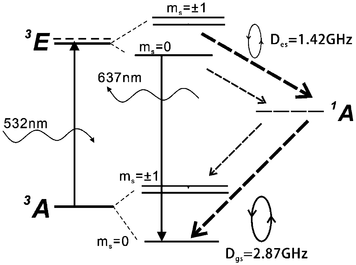
[0094] Figure 4 It shows the frequency modulation ODMR without applying any external magnetic field. The time constant of the lock-in amplifier is set to 30ms, the frequency modulation depth is 2MHz, and the microwave power is 10dbm. It can be clearly seen that there are three characteristic center frequencies f ± , f 0 , which are located at the position with the largest slope. and f 0 ≈(f + +f - ) / 2. Immediately after changing the microwave power and the modulation depth of the microwave, the corresponding microwave power and the value range of the modulation depth under the optimal sensitivity can be obtained.

Embodiment 2

[0096] According to the value range achieved in Embodiment 1, the microwave power and the modulation depth are adjusted to obtain the optimal temperature detection sensitivity.

[0097] First, a coil is used to generate a 1Hz alternating magnetic field (amplitude of 5.2μT), and the center frequency of the microwave is fixed at f ± , f 0 position, and record the change of the signal output by the lock-in amplifier with time. Such as Figure 5 As shown in a, if the center frequency of the microwave is fixed at f ± , the lock-in amplifier outputs a 1Hz oscillating signal, but it is fixed at f 0 , the output signal hardly changes, which shows that the thermometer can isolate the influence of external magnetic field noise. In addition, through numerical analysis, the influence of the geomagnetic field on the temperature detection sensitivity can be ignored.

[0098] Then use an aluminum column to gradually change its distance from the sensor to enhance the influence of metal o...

Embodiment 3

[0102] As for sensitivity, the noise spectral density can be probed, Figure 6 shows that when the microwave frequency is fixed at f 0 , and off the noise spectrum curves of microwaves and lasers, the thermometer invented on the surface has temperature measurement sensitivity, and instrument-limited noise floor


PUM


Abstract

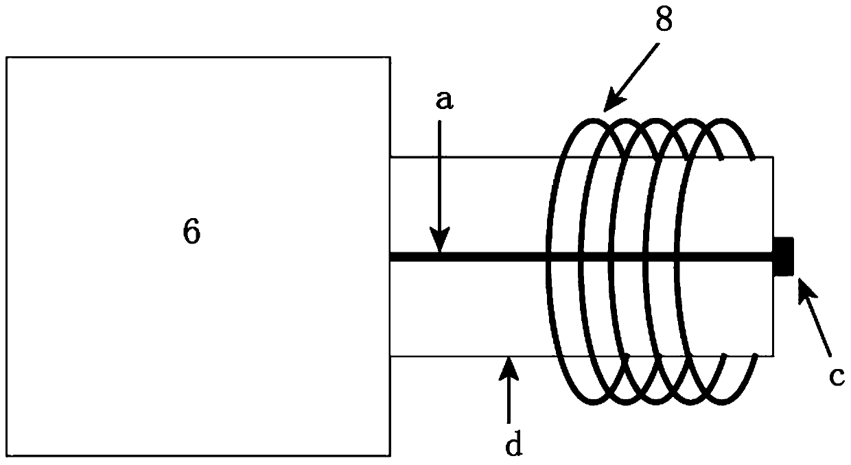
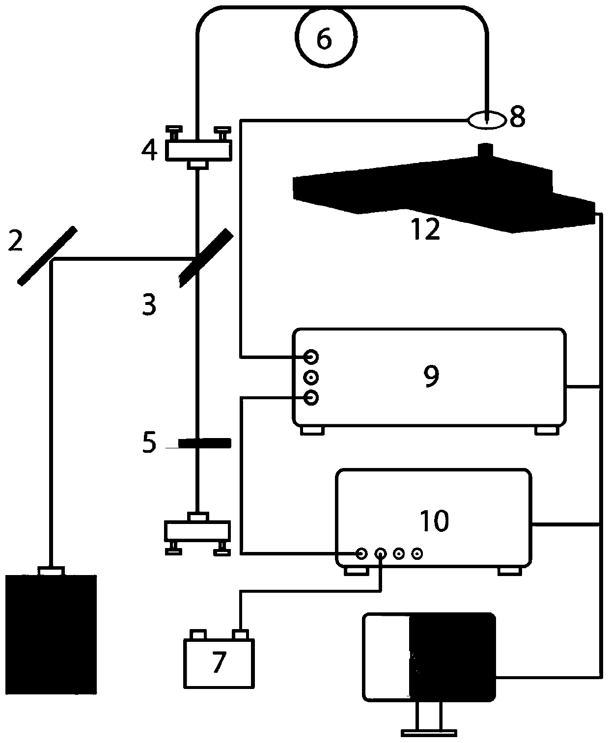
An optical fiber temperature sensor based on a diamond NV color center comprises an optical fiber, a microwave transmission antenna and diamond containing the NV color center, and the optical fiber isused for transmitting exciting light and collecting fluorescence emitted by the NV color center; the microwave transmission antenna is a copper wire surrounding the optical fiber ceramic ferrule andis used for transmitting microwaves to control the ground state energy level of the NV color center so as to perform optical detection magnetic resonance; the diamond containing the NV color center islocated on the end face of the optical fiber, temperature changes can cause changes of the ground state energy level of the NV color center, and then the diamond is used for temperature sensing. Thesensor is simple in structure and high in practicability, high temperature detection sensitivity can be achieved, the sensor is not affected by magnetic field noise and microwave jitter in the environment during detection, and high robustness is reflected. Diamond is used as a main sensing part and has a very high heat conduction coefficient, so that the temperature sensor can respond to millisecond-order temperature change.

Description

technical field [0001] The invention relates to the field of optical fiber fluorescence sensing, in particular to an optical fiber temperature sensor based on a diamond NV color center, a temperature measurement system and a measurement method. Background technique [0002] The development of optical fiber has promoted the innovation of various technologies in recent years, such as optical fiber communication, optical fiber sensing, etc., changing people's lives all the time. Among them, optical fiber sensors have been researched and applied in the measurement of physical quantities such as displacement, vibration, rotation, pressure, bending, speed, acceleration, magnetic field, voltage, humidity, temperature, sound field, PH value, and strain, mainly because optical fibers have excellent Performance, as far as the material itself is concerned, the optical fiber has anti-electromagnetic and atomic radiation interference performance, fine-diameter, soft, light-weight mechani...

Claims


Application Information

Patent Timeline
Patent Type & Authority Applications(China)
IPC IPC(8): G01K11/32
CPCG01K11/3213
Inventor 张少春孙方稳李燊陈向东赵博文郭光灿
Owner UNIV OF SCI & TECH OF CHINA
Learn More