

Voltage regulator circuit
A voltage regulating circuit and resistance technology, which is applied in the direction of adjusting electric variables, control/regulation systems, instruments, etc., can solve the problems of unsuitable integrated circuits, large thyristor area, and large power consumption, etc. Simple structure and low power consumption
- Summary
- Abstract
- Description
- Claims
- Application Information
AI Technical Summary
Problems solved by technology
Method used
Image

Examples
Embodiment Construction
[0008] Below in conjunction with accompanying drawing, the present invention is described in detail.
[0009] In order to make the object, technical solution and advantages of the present invention clearer, the present invention will be further described in detail below in conjunction with the accompanying drawings and embodiments. It should be understood that the specific embodiments described here are only used to explain the present invention, not to limit the present invention.
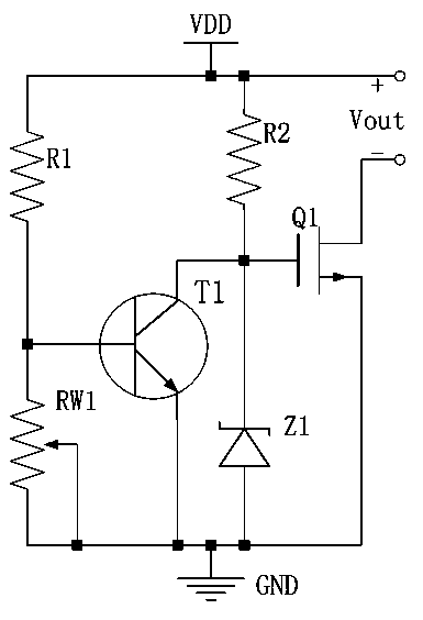
[0010] Such as figure 1 Shown is the circuit schematic diagram of the voltage regulating circuit of the present invention.
[0011] Combine below figure 1 The connection relationship between the above-mentioned electronic components of the present invention is described in detail: a voltage regulating circuit, which includes an NMOS transistor Q1, an NPN bipolar transistor T1, a first resistor R1, a second resistor R2, an adjustable resistor RW1 and Schottky barrier diode Z1; the base of the NP...
PUM
 Abstract
Description
Claims
Application Information