
Core structure of skew-pole rotor of permanent magnet motor and laminating method thereof

A technology of rotor iron core and permanent magnet motor, applied in the direction of magnetic circuit shape/style/structure, electromechanical device, manufacturing motor generator, etc., can solve the problems of reducing motor output power, increasing processing cost, and increasing eddy current loss, etc., to achieve Reduce eddy current loss, improve performance, and reduce the effect of magnetic flux leakage

Inactive Publication Date: 2014-05-07
王必生
View PDF5 Cites 24 Cited by
  • Summary
  • Abstract
  • Description
  • Claims
  • Application Information

AI Technical Summary

Problems solved by technology

[0002] Usually, the rotor of a motor contains an iron core and a shaft, while the rotor of a permanent magnet motor also contains magnetic steel. Different motors have different requirements for their magnetic circuits, and the structure of the rotor will also be different. The structure of the iron core is often made of integral low-carbon steel. Before pasting the magnetic steel, it is necessary to process positioning grooves or positioning ribs on the surface of the rotor core in advance. It is complicated and cannot be carried out with ordinary processing equipment, and the processing of the positioning ribs forming a helix angle with the direction of the rotor axis needs to be carried out with a processing center, which is not only labor-intensive and time-consuming, but also increases processing costs. The eddy current loss will also increase when the motor is running, reducing the output power of the motor

Method used


Image

  • Core structure of skew-pole rotor of permanent magnet motor and laminating method thereof
  • Core structure of skew-pole rotor of permanent magnet motor and laminating method thereof
  • Core structure of skew-pole rotor of permanent magnet motor and laminating method thereof

Examples


Embodiment Construction

[0014] The present invention will be further described in detail below in conjunction with the accompanying drawings and embodiments.

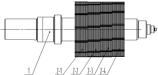
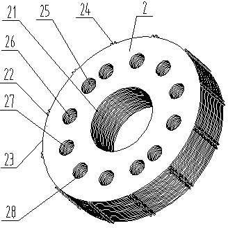
[0015] like figure 1 As shown, the structure and stacking method of the oblique pole rotor core of the permanent magnet motor include the shaft 1 and the rotor core 2. The names and numbers of the rotor core 2-1, the second rotor core 2-2, the third rotor core 2-3 and the fourth rotor core 2-4 are distinguished and expressed to facilitate the description of the embodiments, as image 3 , Figure 4 As shown, the rotor core 2 is provided with a first positioning hole 25 , a second positioning hole 26 , a third positioning hole 27 and a fourth positioning hole 28 . When the rotor is press-fitted, first insert the positioning pin into the first positioning hole 25 of the first rotor core 2-1, the second positioning hole 26 of the second rotor core 2-2, and the positioning pin of the third rotor core 2-3. The third positioning hole 27 and the fo...


PUM


Abstract

The invention discloses a core structure of a skew-pole rotor of a permanent magnet motor and a laminating method of the core structure. The core structure comprises a shaft and rotor cores, wherein the rotor cores are provided with a first locating hole, a second locating hole, a third locating hole and a fourth locating hole respectively. According to the laminating method, the first locating hole of the first rotor core, the second locating hole of the second rotor core, the third locating hole of the third rotor core and the fourth locating hole of the fourth rotor core are located at the same circumferential position through a locating pin, a spiral staggered structure is formed by magnetic steel bonding faces on the rotor cores, and then the skew pole effect of the rotor can be achieved. The core structure of the skew-pole rotor of the permanent magnet motor and the laminating method of the core structure have the advantages that eddy-current loss of the motor can be reduced by the adoption of the laminated structure of the rotor cores, magnetic leakage between adjacent pieces of magnetic steel can be reduced by the arrangement of magnetism isolation grooves, the performance of the motor is improved, the structure is simple, and the machining and manufacturing process is convenient to carry out.

Description

technical field [0001] The invention relates to a rotor structure of a motor, in particular to an oblique pole rotor core structure of a permanent magnet motor. Background technique [0002] Usually, the rotor of a motor contains an iron core and a shaft, while the rotor of a permanent magnet motor also contains magnetic steel. Different motors have different requirements for their magnetic circuits, and the structure of the rotor will also be different. The structure of the iron core is often made of integral low-carbon steel. Before pasting the magnetic steel, it is necessary to process positioning grooves or positioning ribs on the surface of the rotor core in advance. It is complicated and cannot be carried out with ordinary processing equipment, and the processing of the positioning ribs forming a helix angle with the direction of the rotor axis needs to be carried out with a processing center, which is not only labor-intensive and time-consuming, but also increases pro...

Claims


Application Information

Patent Timeline
IPC IPC(8): H02K1/27H02K15/03
CPCH02K2201/06H02K1/278H02K15/03
Inventor 王必生
Owner 王必生
Learn More