Fast recovery circuit

A fast recovery and circuit technology, applied in logic circuits, electrical components, pulse technology, etc., can solve problems such as voltage drop, achieve the effect of improving transient response ability, increasing circuit complexity, and simple structure

Active Publication Date: 2014-05-07
CRM ICBG (WUXI) CO LTD
View PDF4 Cites 1 Cited by
  • Summary
  • Abstract
  • Description
  • Claims
  • Application Information

AI Technical Summary

Problems solved by technology

[0005] The above problem of voltage falling into the invalid region also exists in other circuits

Method used


Image

  • Fast recovery circuit
  • Fast recovery circuit
  • Fast recovery circuit

Examples


Embodiment Construction

[0022] The embodiment of the present invention describes a circuit suitable for fast recovery, which can be connected to a port (usually an output terminal) of the controlled circuit, detect the voltage of the port, and when the detected voltage exceeds the allowable range and enters the invalid region , to pull this voltage out of the invalid region quickly in a pull-up or pull-down manner. This fast recovery circuit is essentially a minimum or maximum voltage clipping circuit. The controlled circuits of the present invention include, but are not limited to, error amplifiers and comparators.

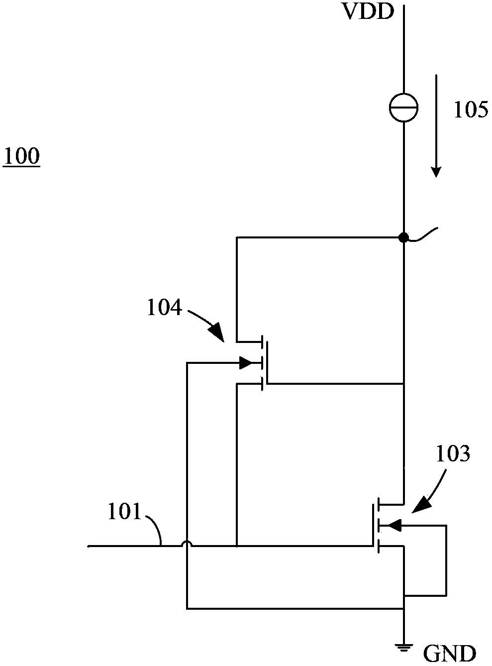
[0023] figure 1 A fast recovery circuit diagram of an embodiment of the present invention is shown. refer to figure 1 As shown, the circuit detects the port that needs to be clipped, and when it detects that the voltage is too low, it injects current into the port to avoid further voltage drop. The fast recovery circuit 100 has an input terminal 101 , a first power supply terminal V...


PUM


Abstract

The invention relates to a fast recovery circuit which is applied to be connected to a port of a controlled circuit such that the voltage of the port is separated from an invalid area rapidly. The fast recovery circuit comprises a first MOS tube, a second MOS tube, an input end, a current injection node, a first power supply terminal, a second power supply terminal and a current source. The input end is connected with the port of the controller circuit. The gate of the first MOS tube is connected with the input end. One of a source electrode and a drain electrode of the first MOS tube is connected with the current injection node, and the other one of the source electrode and the drain electrode is connected with the first power supply terminal or the second power supply terminal. The grid of the second MOS tube is connected with the current injection node. The source electrode and the drain electrode of the second MOS tube are respectively connected with the current injection node. The current source is connected with the current injection node.

Description

technical field [0001] The invention relates to a fast recovery circuit which can make the voltage of one port of the circuit out of invalid area. Background technique [0002] In analog integrated circuits, especially switching power supply chips, error amplifiers and comparators are usually used. The function of the error amplifier is to adjust the control voltage of the error amplifier to change the output voltage according to the voltage values ​​of the positive input terminal and the negative input terminal, so that the positive and negative input terminals are approximately equal. The function of the comparator is to judge the voltage value of the positive-phase and negative-phase input terminals, and express it by the level of the output level. [0003] While the error amplifier is constantly changing at its input, its control voltage is adjusted accordingly. If in a certain state, the control voltage of the error amplifier enters the invalid region, then when the n...

Claims


Application Information

Patent Timeline
IPC IPC(8): H03K19/094
Inventor 刘天罡樊茂
Owner CRM ICBG (WUXI) CO LTD
Why Eureka
Try Eureka