
Rice cooker temperature sensor

A temperature sensor and rice cooker technology, which is applied to thermometers, thermometers and instruments using electrical/magnetic components directly sensitive to heat, etc., can solve the problem of difficult casing collection, inflexible movement of the rice cooker temperature sensor up and down, and poor casing. The problem of gathering in the center, etc., to achieve the effect of improving safety and reliability

Inactive Publication Date: 2015-12-23
GUANGDONG FUER ELECTRONICS
View PDF5 Cites 0 Cited by
  • Summary
  • Abstract
  • Description
  • Claims
  • Application Information

AI Technical Summary

Problems solved by technology

The bundled wire bundles the wires so that they are in the center. However, this method of bundling is only to tighten the bundles of the wires. Because the diameter of the sleeve is much larger than that of the wires, the sleeve is not well gathered in the center, and because the surface of the silicone wire It is relatively slippery, and the binding position is easy to slip away from the casing end during assembly and use. For example, a temperature sensor with double insurance is disclosed in "A New Type of Rice Cooker Temperature Sensor" (Patent No. ZL201220187962.9). There are many tubes, it is difficult to bundle the sleeves well, and if the sleeves are bundled, it cannot be tied tightly because the sleeves are tapered after being bundled.
As a result, the insulating sleeve is easy to scratch with the fixed plate, which will easily cause the temperature sensor of the rice cooker to move up and down flexibly and reduce the insulation performance

Method used


Image

  • Rice cooker temperature sensor
  • Rice cooker temperature sensor
  • Rice cooker temperature sensor

Examples


Embodiment 1

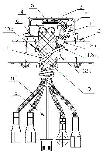
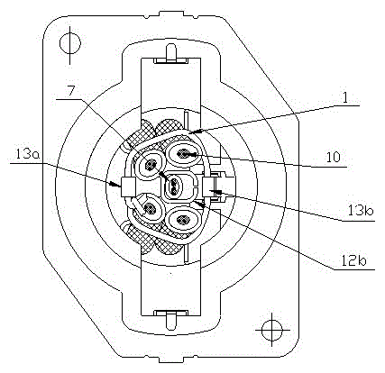
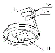
[0017] Such as figure 1 , 2 , 3, and 4, the electric cooker temperature sensor of the present embodiment includes a binding wire 1 and an aluminum cover 2, and a thermistor 3 and a thermal fuse 4 are installed in the aluminum cover 2 through a bracket, and the bracket includes an inner bracket 5 and the outer support 6, the thermistor 3 is fixed on the inner top of the aluminum cover 2 through the inner support 5, and the thermal fuse 4 is fixed at the lower position of the thermistor 3 through the outer support 6;

[0018] The thermistor 3 is set in the first insulating sleeve 7 and connected to the first wire 8 leading out of the aluminum cover 2. The thermal fuse 4 is set in the second insulating sleeve 9 and connected to the lead out It is connected to the second wire 10 outside the aluminum cover 2. The inner bracket 5 is integrally provided with an inner support claw 11 protruding downward. The inner support claw 11 is made of a T-shaped plate, and the horizontal positi...


PUM


Abstract

The invention provides a temperature sensor of an electric cooker. By using the temperature sensor of the electric cooker, insulating bushes and electric wires can be reliably gathered and bundled up; moreover, the temperature sensor of the electric cooker is simple in structure and convenient to mount; and the safety of the electric cooker can be greatly improved. The temperature sensor of the electric cooker comprises a bundling line and an aluminum cover, wherein a thermistor and a hot melting fuse are arranged in the aluminum cover through a support; an insulating bush respectively sleeves the thermistor and the hot melting fuse; the thermistor and the hot melting fuse are respectively connected with a wire which is guided out of the aluminum cover; the support is provided with a supporting claw and a hook; the supporting claw is provided with a U-shaped clamping portion; the insulating bush with the thermistor or / and the hot melting fuse is fixedly clamped by the U-shaped clamping portion; the bundling line is hung in the hook, and two ends of the bundling line are gripped together in a crossed manner after the bundling line wraps the insulating bush; and the two ends of the bundling line wrap the wire by at least one cycle and then are fastened mutually or tightly twined on the wire. By using the supporting claw and the hook, the bundling line, the insulating bush and the wire can be reliably gathered and fixed, and the safety and the reliability of the electric cooker are improved.

Description

technical field [0001] The invention relates to a temperature sensor for an electric rice cooker, in particular to a temperature sensor for an electric rice cooker which can reliably bundle and bundle insulating sleeves and electric wires. Background technique [0002] At present, the temperature sensor of an electric cooker is generally composed of an aluminum cover, a thermistor, a thermal fuse, an electric wire, an insulating sleeve, and a binding wire. The bundled wire bundles the wires so that they are in the center. However, this method of bundling is only to tighten the bundles of the wires. Because the diameter of the sleeve is much larger than that of the wires, the sleeve is not well gathered in the center, and because the surface of the silicone wire It is relatively slippery, and the binding position is easy to slip away from the casing end during assembly and use. For example, a temperature sensor with double insurance is disclosed in "A New Type of Rice Cooker ...

Claims


Application Information

Patent Timeline
Patent Type & Authority Patents(China)
IPC IPC(8): A47J36/00G01K7/22
Inventor 梁其章
Owner GUANGDONG FUER ELECTRONICS
Learn More