
Oblique-inserting type fin evaporator automatic fin-inserting pipe expander

A fin evaporator and oblique insertion type technology, which is applied in the field of inclined insertion type fin evaporator automatic fin tube expansion machine, can solve the problem of poor aluminum pipe threading, strong dependence on worker proficiency, and low operation efficiency. problems, to achieve the effect of improving work efficiency and work safety, shortening the process and production cycle, and reducing the storage of fins

Inactive Publication Date: 2014-05-14
CHANGZHOU CHANGFA REFRIGERATION TECH CO LTD
View PDF8 Cites 10 Cited by
  • Summary
  • Abstract
  • Description
  • Claims
  • Application Information

AI Technical Summary

Problems solved by technology

On each oblique tube expander, 3 people are required to operate, of which 2 people arrange the film and 1 person wears the tube. The number of people employed is relatively large, and the work is purely manual. The labor intensity is high, the work efficiency is low, and it is highly dependent on the proficiency of the workers. More importantly, the quality of sheet arrangement cannot be guaranteed, and there will be various phenomena such as missing arrangement, wrong arrangement, wrong direction of fins, etc., which will lead to poor threading of aluminum tubes and affect production efficiency
At the same time, because the fins are thinner and sharper metal sheets, it is easy to cause work-related accidents such as scratches on the hands of operators.

Method used


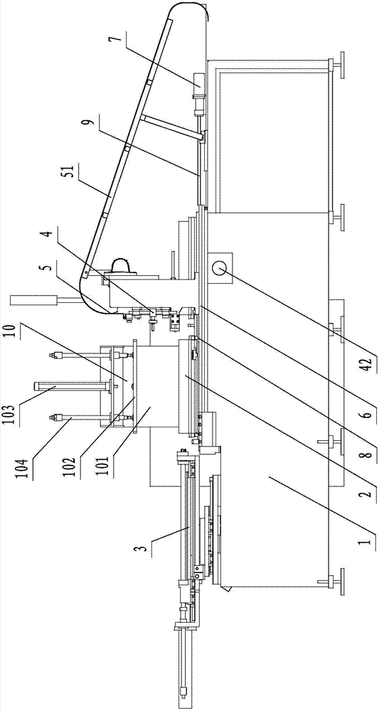
Image

  • Oblique-inserting type fin evaporator automatic fin-inserting pipe expander
  • Oblique-inserting type fin evaporator automatic fin-inserting pipe expander
  • Oblique-inserting type fin evaporator automatic fin-inserting pipe expander

Examples


Embodiment Construction

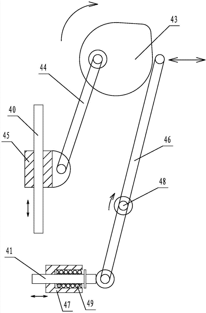
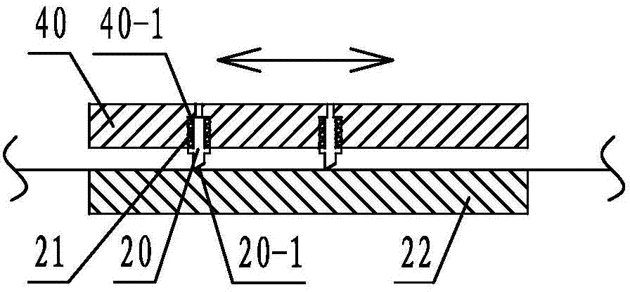
[0017] The present invention will now be further described in conjunction with the accompanying drawings and preferred embodiments. These accompanying drawings are all simplified schematic diagrams, and only illustrate the basic structure of the present invention in a schematic manner, so they only show the configurations related to the present invention, wherein figure 2 , image 3 The middle arrow indicates the direction of motion.

[0018] like Figure 1 ~ Figure 3 An automatic finned tube expander for obliquely inserted finned evaporators is shown, which is used for the arrangement of fins on obliquely inserted finned evaporators and the obliquely inserted and expanded fins and aluminum tubes, including frame 1, On the left side of the table of frame 1, there is a tube expansion device 3 with aluminum tubes placed. The tube expansion device 3 has a propulsion cylinder that pushes the aluminum tubes to penetrate into the fins to insert and tighten them obliquely. The rig...


PUM


Abstract

The invention discloses an oblique-inserting type fin evaporator automatic fin-inserting pipe expander which comprises a machine frame, a fin-inserting die which moves in a stepping mode, a pipe expanding device, a guiding mechanism and a feeding device. The feeding device comprises a material stirring mechanism with a material stirring block, a cutting mechanism with a cutting rod and a cam which is driven by a driving motor to rotate. The cam drives the material stirring block to move up and down in a reciprocating mode to drive a fin to move down in a stepping mode and drives the cutting rod to move horizontally to cut off the fin which moves down. The material stirring block, the cutting rod and the fin-inserting die are matched in a motion-coordination mode. The blank of the fin evaporator industry in China is filled, the material stirring block, the cutting rod and the fin-inserting die are matched in a coordination mode and a stepping-moving mode, automatic fin inserting in the fin-inserting die of the fin is completed, an aluminum pipe is inserted into the fin obliquely through the pipe expanding device for expanding, accordingly, fin inserting, pipe expanding automation and continuity are achieved, the number of workers is reduced, unnecessary labor of fin storing, transferring and the like is lowered, and working efficiency and working safety are improved.

Description

technical field [0001] The invention relates to the technical field of evaporator manufacture, in particular to an automatic fin tube expander for obliquely inserted fin evaporators. Background technique [0002] The evaporator is a very important part of the four major components of refrigeration. The low-temperature condensed "liquid" passes through the evaporator to exchange heat with the outside air, and the "gas" absorbs heat to achieve the effect of refrigeration. Fins: usually on the surface of the heat exchange device that needs heat transfer, metal sheets with strong thermal conductivity are added to increase the heat exchange surface area of ​​the heat exchange device and improve the heat exchange efficiency. Metal sheets with this function are called fins . The fins used on the finned evaporator are generally 0.18mm thick aluminum foil. Inclined insertion: After the aluminum tube is bent, tilted, and flattened, it is pushed up into the fin, so that the aluminum ...

Claims


Application Information

Patent Timeline
IPC IPC(8): B21D53/08
Inventor 陈建东顾柳青
Owner CHANGZHOU CHANGFA REFRIGERATION TECH CO LTD
Learn More