Vehicle air conditioner

A vehicle air conditioner and vehicle technology, which is applied to vehicle components, air handling equipment, heating/cooling equipment, etc., can solve problems such as abnormal noise, and achieve the effect of suppressing abnormal noise

Inactive Publication Date: 2014-05-14
MITSUBISHI MOTORS CORP
View PDF5 Cites 19 Cited by
  • Summary
  • Abstract
  • Description
  • Claims
  • Application Information

AI Technical Summary

Problems solved by technology

This causes problems such as abnormal noise when switching between cooling and heating operating modes

Method used


Image

  • Vehicle air conditioner
  • Vehicle air conditioner
  • Vehicle air conditioner

Examples


Embodiment Construction

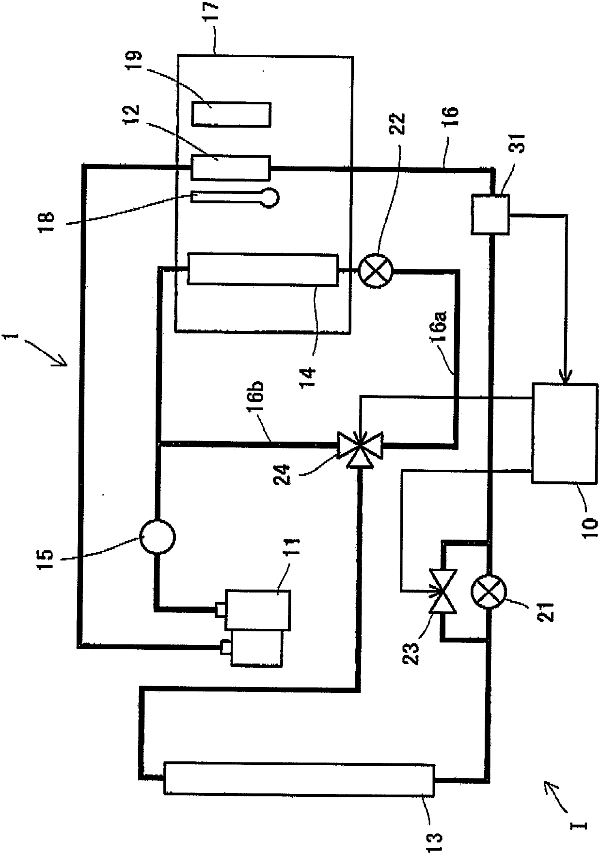
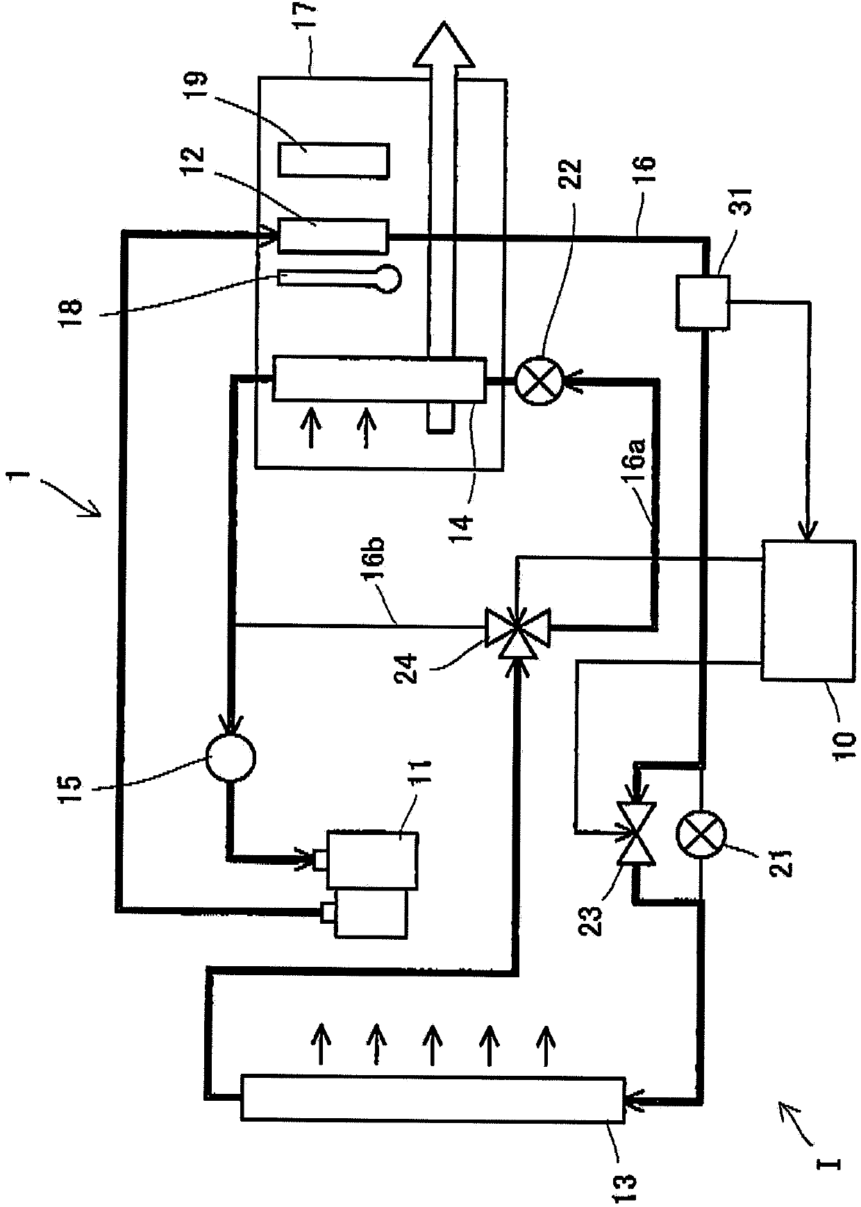
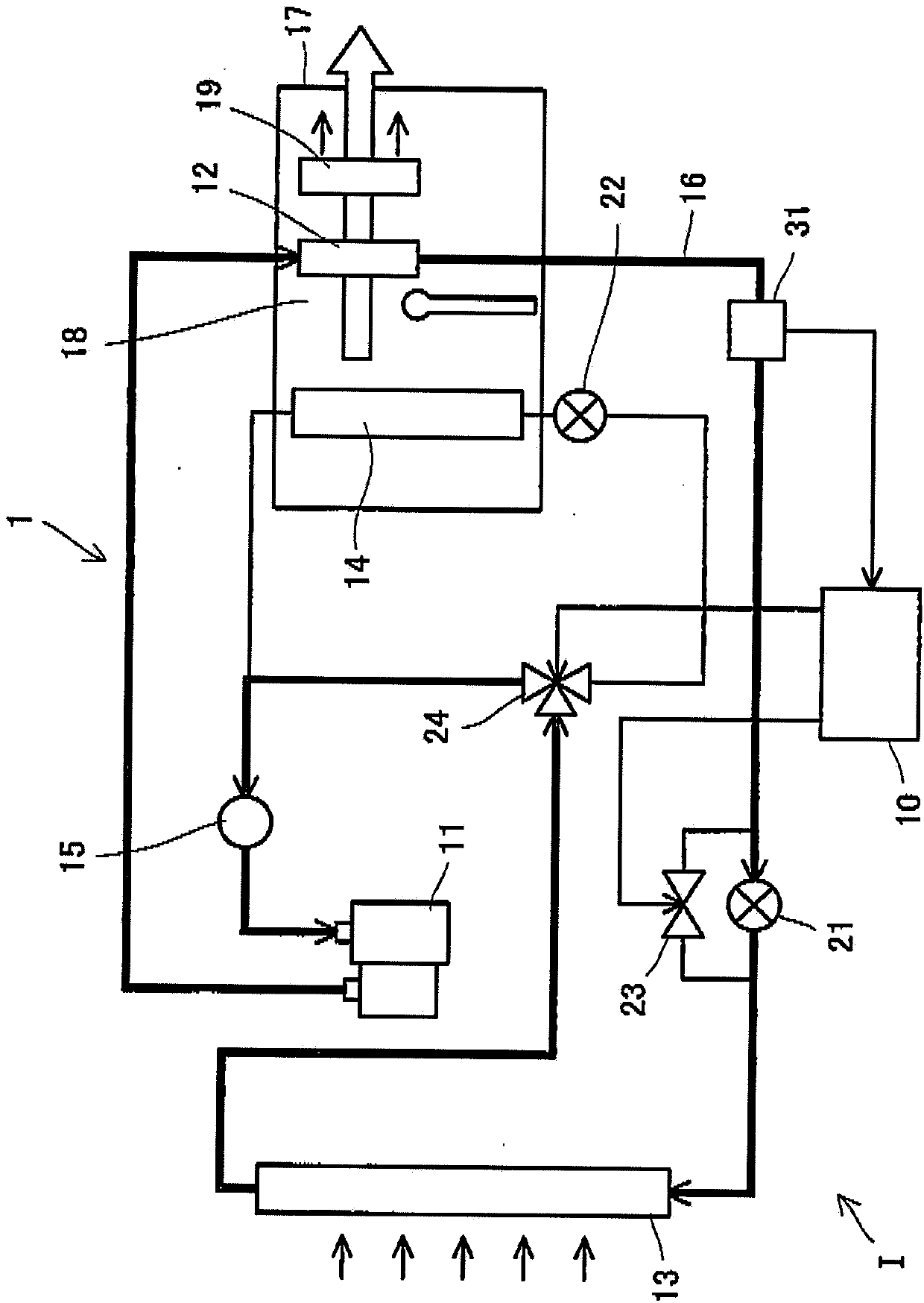
[0041] First, refer to figure 1 A heat pump system for a vehicle air conditioner according to an embodiment of the present invention will be described.

[0042] The vehicle air conditioner 1 has a heat pump system 1 . The heat pump system 1 is equipped with an electric compressor (compression device) 11, a vehicle interior condenser (heat exchanger) 12, a vehicle exterior condenser (heat exchanger) 13, an evaporator (heat exchanger) 14, a storage 15, a an expansion valve (pressure reducing device) 21, and a second expansion valve (pressure reducing device) 22. These components are connected by pipes 16 constituting flow channels for the heating medium. The heat pump system 1 is provided with a flow path having a cooling path and a heating path whose details will be described later. The cooling path is a path through which a heating medium flows during cooling, and the cooling path passes through the electric compressor 11 , the vehicle interior condenser 12 , the vehicle ex...


PUM


Abstract

A vehicle air conditioner, which can suppress the occurrence of an abnormal noise when switching the operation mode of air conditioning, is provided. The vehicle air conditioner comprises compression means for compressing a heating medium, pressure reducing means for reducing the pressure of the heating medium, a heat exchanger for performing heat exchange between the heating medium and air, a flow passage having a heating path and a cooling path, a flow passage selector valve for changing the path in the flow passage, and a control unit for allowing the flow passage selector valve to act in accordance with an air conditioning operation mode. If a switching instruction on the air conditioning operation mode is inputted, the control unit stops the compression means and also defers the action of the flow passage selector valve until a predetermined time elapses or until a pressure difference between the paths becomes a predetermined value or less.

Description

technical field [0001] The invention relates to a vehicle air conditioner. Background technique [0002] Hitherto, a heat pump system (vapour-compression refrigeration system) having a compressor, a vehicle interior condenser, a vehicle exterior condenser, a vehicle interior evaporator and a pressure reduction device is known as a vehicle air conditioner. With an electric vehicle, unlike a motor vehicle, the interior of the vehicle cannot be heated with heat from a driving source, and thus such a heat pump system is employed (for example, see Patent Document No. JP-A-2011-240725). The heat pump system described in the above patent documents includes: a flow path for cooling, wherein at the time of cooling, the internal evaporator causes the expanded heating medium to undergo heat exchange with the cooling air when the pressure reduction device performs pressure reduction; and In a heated runner, where the internal condenser causes the heating medium compressed by the compre...

Claims


Application Information

Patent Timeline
Patent Type & Authority Applications(China)
IPC IPC(8): B60H1/00
CPCB60H1/00899B60H1/00921B60H1/3213B60H2001/00935B60H2001/327B60H2001/3292
Inventor 森高篤司藤原晋哉梅津康平
Owner MITSUBISHI MOTORS CORP
Why Eureka
Try Eureka