Vacuum evaporation source capable of being mounted at any angle for use

A technology of vacuum evaporation and any angle, which is applied in the direction of vacuum evaporation plating, ion implantation plating, metal material coating process, etc., and can solve problems such as the interface is in an idle state, the number of available interfaces is reduced, and the upward interface is not enough.

Active Publication Date: 2014-05-14
苏州驰鸣纳米技术有限公司
View PDF4 Cites 3 Cited by
  • Summary
  • Abstract
  • Description
  • Claims
  • Application Information

AI Technical Summary

Problems solved by technology

Electron beam evaporation sources are generally used for evaporation of materials with high melting points, but the disadvantage is that the structure of the evaporation source is complex and difficult to maintain
[0005] However, in some cases, the evaporation source with the evaporation port facing up also has disadvantages: 1. The growth surface of the substrate must face down; 2. It brings great inconvenience to the monitoring of the growth process; 3. It reduces the Possibility of using the interface
Since the formal-mounted evaporation source can only be installed upwards, the downward-facing interface is often idle, so it often happens that the upward-facing interface is not enough and the downward-facing interface is not available.

Method used


Image

  • Vacuum evaporation source capable of being mounted at any angle for use
  • Vacuum evaporation source capable of being mounted at any angle for use
  • Vacuum evaporation source capable of being mounted at any angle for use

Examples


Embodiment Construction

[0023] The preferred embodiments of the present invention will be described in detail below with reference to the accompanying drawings.

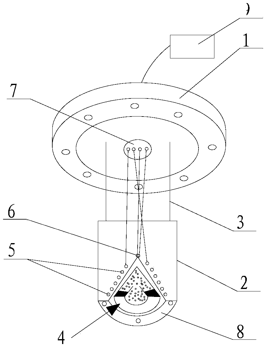
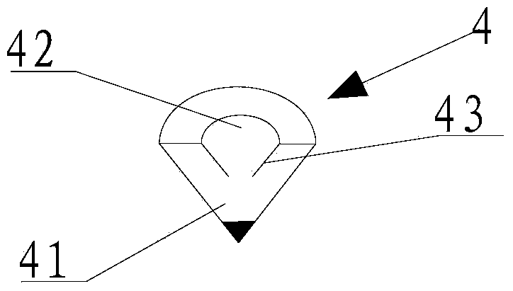
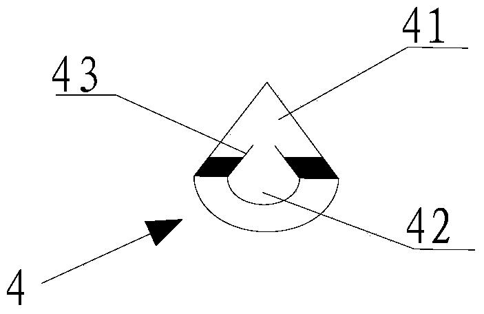
[0024] Such as Figures 1 to 2 The shown vacuum evaporation source mainly includes a vacuum flange 1 , a heat shielding component 2 , a container 4 , a heating component 5 , a temperature measuring component 6 and a vacuum electrical connector 7 .

[0025] Among them, the vacuum flange 1 can be used to support the heat shield assembly 2; the container 4 is detachably embedded in the end of the heat shield assembly 2 away from the vacuum flange 1, and is used to hold the evaporation material; the heating assembly 5 is fixed in the heat shield assembly 2 , for the built-in container 4 and thereby it is heated; the temperature measuring assembly 6 is installed near the container 4, and is used to measure the temperature of the container 4; the vacuum electrical connector 7 is installed on the vacuum flange 1, respectively with the heating asse...


PUM


Abstract

The invention relates to a vacuum evaporation source capable of being mounted at any angle for use. The vacuum evaporation source comprises a heat shield assembly, a vacuum flange, a container, a heating assembly which is fixed in the heat shield assembly and is built in the container, a temperature measurement assembly, and a vacuum electric connector which is mounted on the vacuum flange and is electrically connected with the heating assembly and the temperature measurement assembly, wherein the container is detachably embedded at one end, far away from the vacuum flange, of the heat shield assembly and is provided with an inner cavity; an opening communicated with the inner cavity is formed in one end, far away from the vacuum flange, of the container; a circumferential wall extending into the inner cavity is arranged at the opening; the end, extending into the inner cavity, of the circumferential wall is open; the area of the circumferential wall is smaller than that of the inner cavity in the same plane with the circumferential wall. Therefore, an evaporation material can be prevented from falling from the opening when the vacuum evaporation source is tilted or inverted.

Description

technical field [0001] The invention relates to a vacuum evaporation source, in particular to a vacuum evaporation source which can be installed and used at any angle. Background technique [0002] Vacuum evaporation deposition is a conventional thin film preparation method, which has the characteristics of high material utilization efficiency, simplicity, good uniformity and high controllability. It is widely used in the deposition of inorganic semiconductor materials, metals, organic semiconductor materials and other functional materials. film production. Generally speaking, vacuum evaporation deposition is to place the evaporated source material in a material container, and vaporize the source material through different heating methods, so as to generate atomic, molecular or cluster beams of the source material without collision in vacuum Deposited on a substrate, the growth rate can be determined by the temperature of the source material. The devices that generate ato...

Claims


Application Information

Patent Timeline
Patent Type & Authority Applications(China)
IPC IPC(8): C23C14/24
Inventor 迟力峰王文冲
Owner 苏州驰鸣纳米技术有限公司
Why Eureka
Try Eureka