Improved siphon circulation hydroelectric generation device

A hydroelectric power generation device and improved technology, applied in the directions of hydroelectric power generation, engine components, machines/engines, etc., can solve problems such as affecting the quality of power supply, flooding people and property, aggravating cavitation, etc., so as to prolong the time of emergency power generation and protect people's lives. and property safety, avoid the effect of vacuum negative pressure

Inactive Publication Date: 2014-05-14
何其兴
View PDF6 Cites 1 Cited by
  • Summary
  • Abstract
  • Description
  • Claims
  • Application Information

AI Technical Summary

Problems solved by technology

[0003] After several years of use, it is found that the device still has some deficiencies. Firstly, the siphon is set up vertically, and the air is not easy to discharge when filling the water storage tank. Cavitation often occurs during the power generation process of circulating water, and the generator set operates unevenly. , the second is that the matching between the siphon tube and the water inlet pipe of the generator is unreasonable, so that the water outlet of the water storage tank is too fast, and the siphon water supply is too slow, which will cause a vacuum inside the water storage tank, and the internal and external pressure is too large, which will damage the water storage tank and cause Safety accidents, also due to the frequent occurrence of vacuum (negative pressure) inside the water storage tank, aggravated cavitation, resulting in large changes in the running speed of the water wheel, abnormal power generation, and affecting the quality of power supply
With the increase of the capacity of the water storage tank and the improvement of the specification of the generator, this problem becomes more and more prominent, especially when the water storage tank bursts due to the increase of vacuum negative pressure, a large amount of accumulated water will flow out, which will make the entire farmyard It will soon turn into a flood country, causing floods and loss of personal property

Method used


Image

  • Improved siphon circulation hydroelectric generation device
  • Improved siphon circulation hydroelectric generation device
  • Improved siphon circulation hydroelectric generation device

Examples


Embodiment Construction

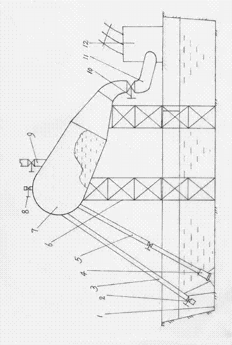
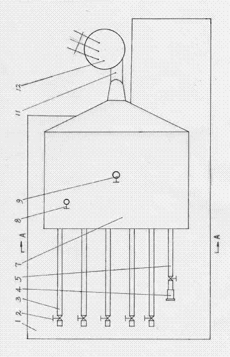
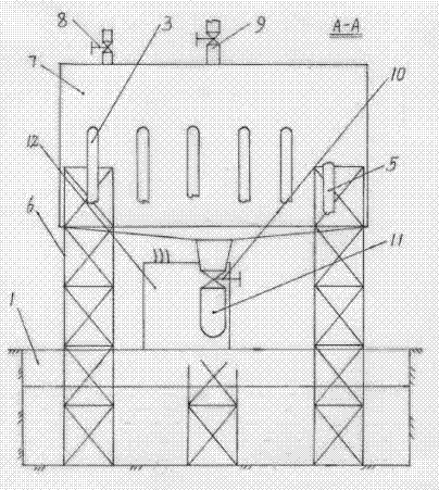
[0021] Such as Figure 1-3 As shown, the water storage tank 7 is a general box or tank structure, which is welded with steel plates. In order to ensure its strength, welding stays can be added between the tank walls to ensure that when the vacuum negative pressure suddenly appears in the tank Counteract the external pressure and avoid the tank from sinking and bursting. For ordinary rural residents, emergency power generation is generally considered to be installed within the specification of 10KW. Therefore, the thickness of the steel plate of the tank body is 5-10mm, and the volume of the tank body is within 100 cubic meters. If greater emergency power generation capacity is required, the tank body should be designed with greater pressure-bearing materials. The setting of the height of the tank body must also be compatible with the corresponding power generation capacity. The safety hazard of pipeline burst. For general users, the drop between the top of the water storage...


PUM


Abstract

The invention relates to an improved siphon circulation hydroelectric generation device which is composed of a water storage tank, a siphon pipe, a buffering water tank and an electric generator. The water storage tank is arranged above the buffering water tank, the siphon pipe is a slant pipe connected between the water storage tank and the buffering water tank, the low end of the siphon pipe is provided with a siphon pipe bottom valve, the bottom of the water storage tank is provided with a water inlet pipe connected with the electric generator, a blowoff valve is arranged at the top of the water storage tank, a water feeding pipe is connected between the water storage tank and the buffering water tank, the low end of the water feeding pipe is provided with a pump and a gate valve, the water passing cross sectional area of the siphon pipe is larger than or equal to the water passing cross sectional area of the water inlet pipe, and the blowoff valve is an automatic stopping valve in water level signal linkage with the water storage tank. When water is fed into the water storage tank, the blowoff valve is opened, air in the water storage tank is discharged, and the blowoff valve is automatically closed when the water storage tank is filled with the water and the water is overflowed. According to the improved siphon circulation hydroelectric generation device, the surging hidden dangers of the negative pressure in the electric generation process are eliminated, the amount of the water coming in and going out of the water storage tank is basically balanced, generation of the in-tank vacuum negative pressure is avoided, gentle releasing of water energy in the water storage tank is guaranteed, the electric generation quality is improved, the potential safety hazard that the water storage tank is cracked is eliminated, and the personal and property safety is guaranteed.

Description

technical field [0001] The invention is an energy storage power generation tool used at home in a rural area in a power shortage area, and an improved siphon circulation hydroelectric power generation device. It can also be used for emergency use by small units. Background technique [0002] The utility model patent with the notification number CN200975313Y, "siphon circulation hydroelectric power generation device" is an invention created by the applicant earlier. In rural areas with little rain and electricity shortage, especially in mountainous areas, the device solves the problem of partial electricity consumption to a certain extent, and obtains certain economic and social benefits. [0003] After several years of use, it is found that the device still has some deficiencies. Firstly, the siphon is set up vertically, and the air is not easy to discharge when filling the water storage tank. Cavitation often occurs during the power generation process of circulating water,...

Claims


Application Information

Patent Timeline
Patent Type & Authority Applications(China)
IPC IPC(8): F03B13/06
CPCY02E10/20Y02E60/16Y02P90/50
Inventor 何其兴
Owner 何其兴
Why Eureka
Try Eureka