

Second-generation tapered roller bearing of speed reducer industry
A technology of tapered roller bearings and reducers, which is applied in the field of bearings, can solve the problems that the machining accuracy of the spacer ring affects the installation accuracy, etc., and achieve the effects of compact structure, improved load distribution, and increased service life
Inactive Publication Date: 2014-05-14
UBC SHANGHAI PRECISION BEARING MFG
View PDF9 Cites 0 Cited by
- Summary
- Abstract
- Description
- Claims
- Application Information
AI Technical Summary
Problems solved by technology
[0002] At present, the reducer adopts the worm gear structure. The most widely used reducer bearings are single-row tapered roller bearings or back-to-back paired tapered roller bearings. Due to the processing accuracy of the spacer ring, the installation accuracy is affected.
Therefore, the most challenging thing in the reducer industry is the application of bearings.
Method used
View moreImage
Smart ImageViewing Examples

Examples
Embodiment
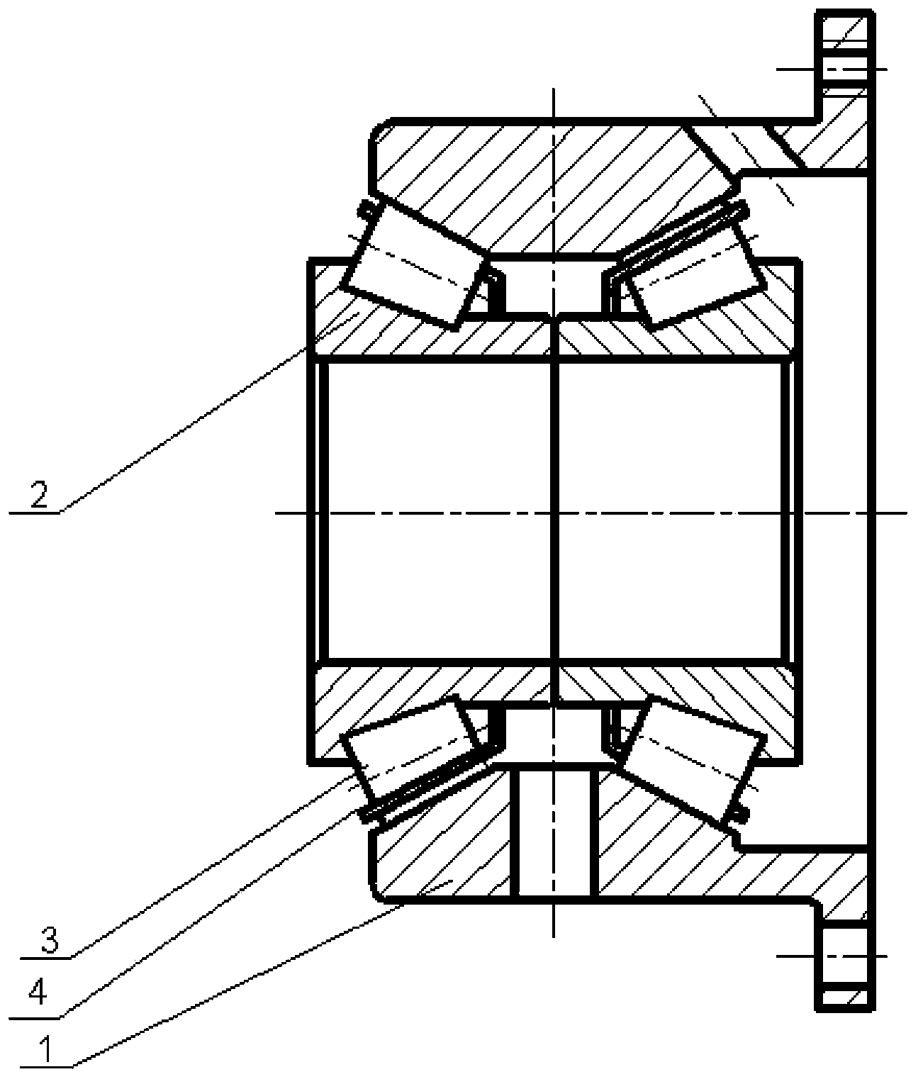
[0018] Such as figure 1 As shown, a second-generation tapered roller bearing in the reducer industry includes an inner ring 2, an outer ring 1, a roller 3 and a cage 4. The cage 3 installs the rollers in its pockets and is connected with After the inner ring 2 is connected, it is put into the double-row raceway of the outer ring 1 together.
[0019] The outer ring 1 is a flange structure, and is provided with an oil filling hole communicating with the inner ring 2 . There are two inner rings 2, and the outer walls of the two inner rings 2 form a back-to-back raceway structure. The outer ring 1 is an outer ring made of spring steel after surface quenching. The bearing should form a certain torque.
Login to View More PUM
 Abstract
The invention relates to a second-generation tapered roller bearing of the speed reducer industry. The second-generation tapered roller bearing comprises an inner ring, an outer ring, rollers and a retainer; through the retainer, the rollers are arranged in a pocket hole of the retainer; and the rollers and the inner ring which are connected with each other are packed into double rows of raceways of the outer ring. Compared with the prior art, the second-generation tapered roller bearing provided by the invention has the advantages of compact structure, convenience for assembling, good lubrication effect and long service life.
Description
technical field [0001] The invention relates to a bearing, in particular to a second-generation tapered roller bearing in the reducer industry. Background technique [0002] At present, the reducer adopts worm gear structure. The most widely used reducer bearings are single-row tapered roller bearings or back-to-back paired tapered roller bearings. Due to the processing accuracy of the spacer ring, the installation accuracy is affected. Therefore, the more challenging part in the reducer industry is the bearing application. The bearings in the key parts of the reducer will be in the operating environment of heavy load, impact load, high and low speed, high temperature and high pollution. The bearing in the reducer equipment can be said to be the heart of the reducer. It is precisely because of this harsh operating environment that the demand for high-performance bearings has arisen. Only high-performance bearings can ensure the maximum continuous operation of the reducer i...
Claims
Login to View More Application Information
Patent Timeline
 Patent Type & AuthorityApplications(China)
IPC IPC(8): F16C19/38F16C33/58F16C33/62F16C33/66
CPCF16C19/386
Inventor卢天民
OwnerUBC SHANGHAI PRECISION BEARING MFG