Brake device of unmanned aerial vehicle rotor wing

A technology of a braking device and a rotor of an aircraft is applied in the field of braking devices, which can solve the problems of inconvenient detection and maintenance, shorten the service life of gears, reduce the strength of gears, etc., and achieve the effects of simple structure, reduction of main shaft gear wear, and increased stability.

Active Publication Date: 2014-05-14
天津凤凰智能科技有限公司
View PDF7 Cites 8 Cited by
  • Summary
  • Abstract
  • Description
  • Claims
  • Application Information

AI Technical Summary

Problems solved by technology

The disadvantages are: a cavity is set inside the gear, which reduces the strength of the gear and shortens the service life of the gear; the eccentric friction block of the deceleration

Method used


Image

  • Brake device of unmanned aerial vehicle rotor wing
  • Brake device of unmanned aerial vehicle rotor wing

Examples


Embodiment 1

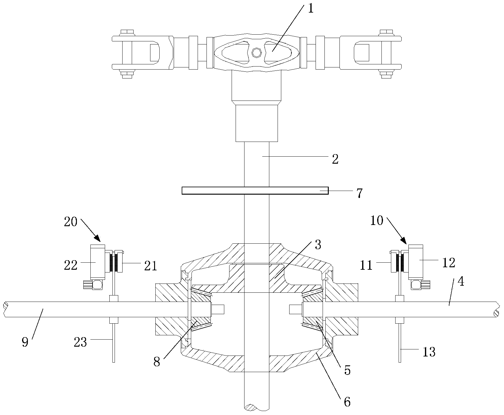
[0020] Such as figure 1 and figure 2 As shown, the UAV rotor brake device of the present invention, its rotor comprises rotor head 1 and main shaft 2, and main shaft 2 is provided with concentric main shaft gear 3; The concentric driving gear 5 at the end, the brake disc A13 set on the driving shaft 4, the driven shaft 9, the concentric driven gear 8 fixed on the input end of the driven shaft 9, and the brake disc B23 set on the driven shaft 9 , the brake disc A13 is provided with a brake component A10, and the brake disc B23 is provided with a brake component B20; the driving gear 5 and the driven gear 8 are arranged concentrically and symmetrically, and the main shaft gear 3 is connected with the driving gear 5 and the driven gear 8 respectively. meshing, main shaft gear 3, driving gear 5 and driven gear 8 are all spiral bevel gears.

Embodiment 2

[0022] Except following difference, other is with embodiment 1.

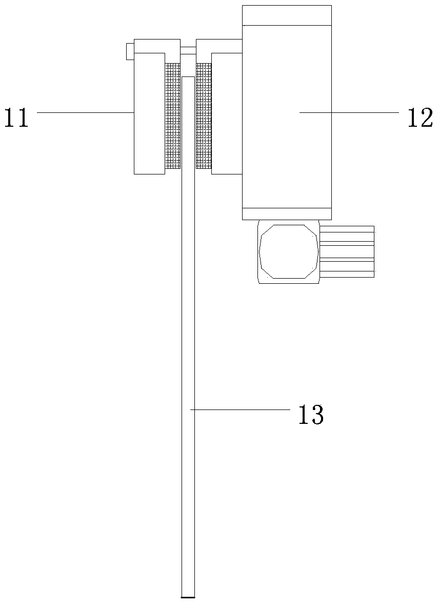
[0023] The braking unit A10 includes a brake pad A11 and a servo A12 that controls the brake pad A11.

[0024] The braking unit B20 includes a brake pad B21 and a servo B22 that controls the brake pad B21.

Embodiment 3

[0026] Except following difference, other is with embodiment 2.

[0027] The main shaft gear 3 , the driving gear 5 and the driven gear 8 are covered with a gate box 6 .


PUM


Abstract

The invention relates to a brake device of an unmanned aerial vehicle rotor wing. The brake device comprises a drive shaft, a concentric drive gear, a brake disc A, a driven shaft, a concentric driven gear and a brake disc B. The concentric drive gear is fixedly connected to the output end of the drive shaft, the brake disc A is arranged on the drive shaft, the concentric driven gear is fixedly connected to the input end of the driven shaft, and the brake disc B is arranged on the driven shaft. The rotor wing comprises a rotor wing head and a main shaft, and a concentric main shaft gear is arranged on the main shaft. A brake component A is arranged on the brake disc A of the brake device, and a brake component B is arranged on the brake disc B. The drive gear and the driven gear are symmetrically arranged in a concentric mode, the main shaft gear is respectively meshed with the drive gear and the driven gear, and the main shaft gear, the drive gear and the driven gear are spiral beveled gears. In the prior art, when the main shaft gear brakes for deceleration, abrasion, caused by relative torsion and stress concentration, to the main shaft gear is reduced, and stability is improved when the rotor wing decelerates for transmission.

Description

technical field [0001] The invention belongs to the technical field of braking devices, and in particular relates to a braking device applied to the rotor of an unmanned aerial vehicle. Background technique [0002] With the development of UAV technology, especially the rapid development of unmanned helicopters, its application is becoming wider and wider, and it is indispensable in both civilian and military fields. However, when the unmanned helicopter is operating in the air, the engine drives the rotor to rotate extremely fast, the sweeping area of ​​the rotor is relatively large, and the inertia of the fuselage and the rotor is relatively large during motion. When the rotor is out of control, if it cannot be braked in time, its powerful destructive force may cause great harm to the ground crowd or buildings. [0003] Chinese patent CN203009640U discloses a braking device for an unmanned rotor helicopter in the air. Its structure is: a cavity is provided inside the conc...

Claims


Application Information

Patent Timeline
IPC IPC(8): F16D55/22B64C27/59
Inventor 李琰玥
Owner 天津凤凰智能科技有限公司
Why Eureka
Try Eureka