
Electric-propulsion joint loading test system

A combined loading and testing system technology, applied in the field of testing systems, can solve problems such as small loading range, single loading method, and low loading fault tolerance rate, and achieve the effect of improving accuracy and flexibility and realizing large-scale loading

Inactive Publication Date: 2014-05-14
HARBIN ENG UNIV
View PDF4 Cites 2 Cited by
  • Summary
  • Abstract
  • Description
  • Claims
  • Application Information

AI Technical Summary

Problems solved by technology

However, most of the current motor loading systems control a single motor as a loading system, with a single loading method, a small loading range, and a low loading fault tolerance rate.

Method used


Image

  • Electric-propulsion joint loading test system

Examples


Embodiment Construction

[0012] The present invention is described in more detail below in conjunction with accompanying drawing example:

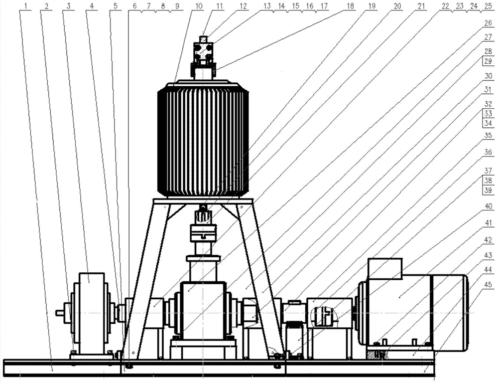
[0013] combine figure 1 The transmission device involved in the present invention is composed of the following components: magnetic powder brake base 1, screw 2, magnetic powder brake 3, coupling 4, base 5, bolt 6, washer 7, washer 8, nut 9, permanent magnet motor 10, Transmission body 11, polished rod 12, splint 13, bolt 14, nut 15, washer 16, washer 17, transmission key 18, screw 19, key 20, coupling 21, protective cover 222, screw 23, washer 24, washer 25, Commutator 26, bolt 27, panel 28, screw 29, permanent magnet machine bracket 30, coupling 31, torque sensor 32, bolt 33, washer 34, protective cover 135, coupling 36, torque sensor seat 37, screw 38. Washer 39, bolt 40, six-phase motor 41, bolt 42, screw 43, motor backing plate 44, motor base 45.

[0014] Screws 28 fix the commutator 26 on the base 5 , and bolts 27 fix the panel 28 on the permanent magnet m...


PUM


Abstract

The invention provides an electric-propulsion joint loading test system. A magnetic powder brake is installed on a magnetic powder brake base, a reversing device is installed on a base, a six-direction motor is installed on a motor cushion plate installed on a motor base, a permanent-magnetism motor is installed on a permanent-magnetism motor support fixed to the base, the reversing device is located on the permanent-magnetism motor support and below the permanent-magnetism motor, the magnet powder brake base, the base and the motor base are sequentially connected, a torque sensor is installed on the motor base through a torque sensor base connected with the permanent-magnetism motor support, the magnet powder brake is connected with a left opening of the reversing device, a right opening of the reversing device is connected with the torque sensor connected with the six-direction motor, and an upper opening of the reversing device is connected with the permanent-magnetism motor. The electric-propulsion joint loading test system overcomes defects of a single motor or magnetic powder brake loading system and further improves motor loading accuracy and flexibility.

Description

technical field [0001] The present invention relates to a test system, specifically a loading test system. Background technique [0002] The loading system is also a load simulator, which is widely used in force (moment) servo systems such as hydrodynamic loading experiments on ship rudder surfaces and aerodynamic loading experiments on aircraft rudder surfaces. In the past, electro-hydraulic servo valves were used to control hydraulic motors or magnetic powder brakes as the actuators of the loading system, which were called electro-hydraulic servo loading systems and magnetic powder brake loading systems. [0003] In recent years, with the development of high-power power electronic devices and the improvement of motor performance, an electric servo loading system composed of DC or AC motors as actuators has appeared in the small torque range. However, most of the current motor loading systems control a single motor as a loading system, with a single loading method, a small...

Claims


Application Information

Patent Timeline
Patent Type & Authority Applications(China)
IPC IPC(8): G01M10/00
Inventor 李冰智鹏飞刘胜程垠钟李相武
Owner HARBIN ENG UNIV
Learn More