Imaging locating method of optical touch module and optical touch control equipment

A technology of optical touch and positioning method, which is applied in the field of image processing, and can solve the problems of poor anti-light ability, inability to eliminate screen touch space interference, and inability to distinguish the type of touch objects, etc.

Active Publication Date: 2014-05-14
TIANJIN XITONG ELECTRONICS EQUIP CO LTD
View PDF5 Cites 17 Cited by
  • Summary
  • Abstract
  • Description
  • Claims
  • Application Information

AI Technical Summary

Problems solved by technology

[0022] A) The number of points is small, and the touch cannot be perfect;
[0023] B) There are congenital defects in the distribution of the lens, and it is impossible to touch the whole screen accurately;
[0024] C) The line-column signal cannot rule out the interference that occurs in the screen touch space;
[0025] D) Without redundancy, if one camera is abnormal, the whole device cannot be used;
[0026] E) Unable to distinguish the type of touch object;
[0027] F) The ability to resist light is poor, and it cannot be used normally when exposed to direct sunlight

Method used


Image

  • Imaging locating method of optical touch module and optical touch control equipment
  • Imaging locating method of optical touch module and optical touch control equipment
  • Imaging locating method of optical touch module and optical touch control equipment

Examples


Embodiment Construction

[0086] Embodiments of the present invention are described in detail below, examples of which are shown in the drawings, wherein the same or similar reference numerals designate the same or similar elements or elements having the same or similar functions throughout. The embodiments described below by referring to the figures are exemplary and are intended to explain the present invention and should not be construed as limiting the present invention.

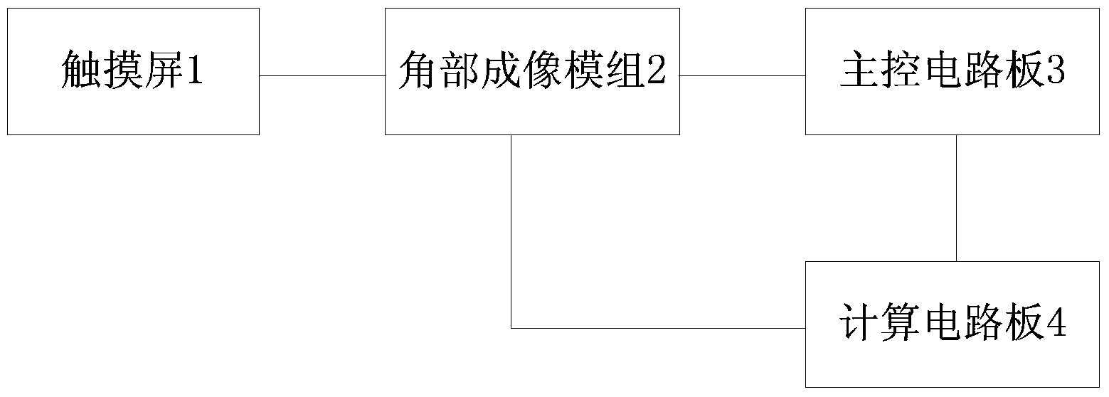
[0087] The imaging positioning method of the optical touch module of the present invention comprehensively utilizes hardware and software parts, wherein the hardware part mainly includes a touch screen and its control equipment for realizing signal acquisition. The software part is mainly to detect, locate, track and send contacts based on the data collected by the hardware.

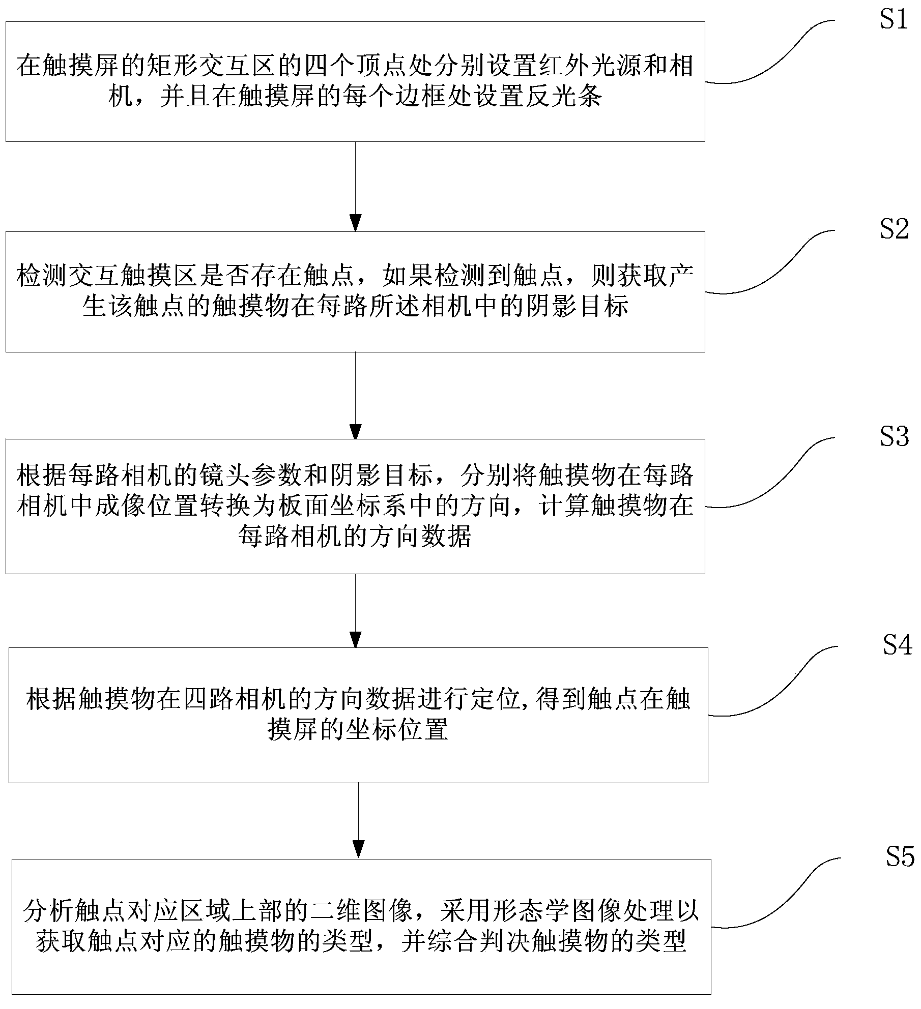
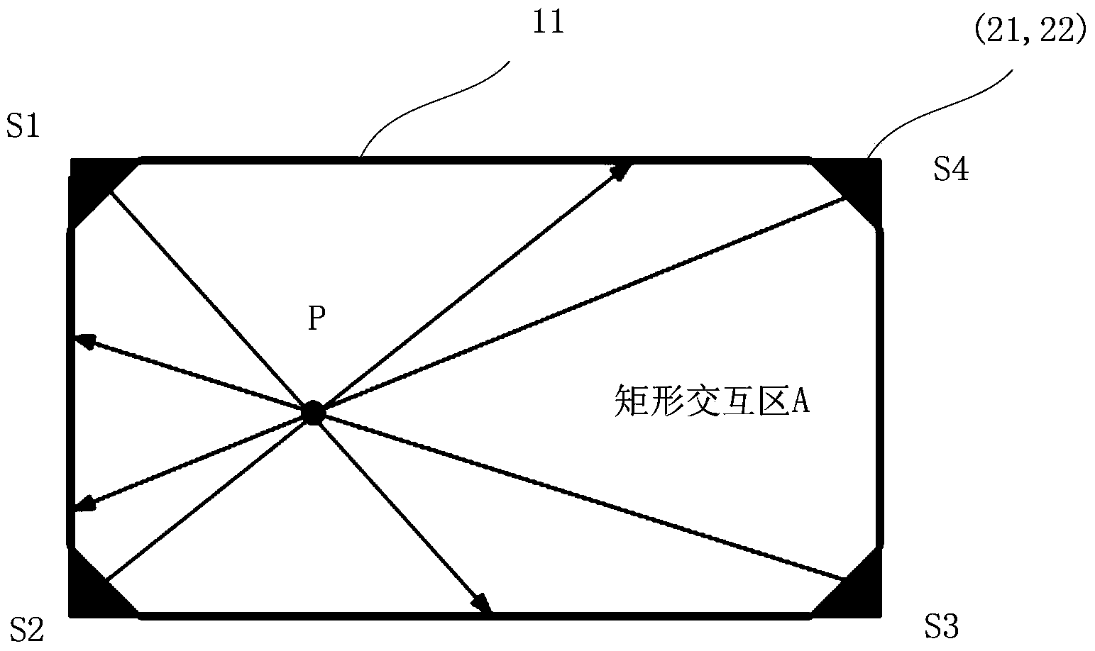
[0088] Refer below figure 1 The imaging positioning method of the optical touch module according to the embodiment of the present invention will be descri...


PUM


Abstract

The invention provides an imaging locating method of an optical touch module. The imaging locating method of the optical touch module comprises the steps that infrared light sources and cameras are arranged at the positions of four vertex points of a rectangular interaction area of a touch screen and a reflection strip is arranged at the position of each frame of the touch screen; whether a touch point exists in the interaction touch area or not is detected, and if yes, a shadow target, in each camera, of a touch object generating the touch point is obtained; an imaging position, in each camera, of the touch object is converted into a direction in a board coordinate system and direction data, in each camera, of the touch object are calculated; locating is conducted according to the direction data, in the four cameras, of the touch object to obtain the coordinate position, on the touch screen, of the touch point; a two-dimensional image of the upper portion of an area corresponding to the touch point is analyzed, and morphology imaging processing is adopted so as to obtain the type of the touch object corresponding to the touch point. The invention further provides optical touch control equipment. The imaging locating method of the optical touch module and the optical touch control equipment can realize multi-point touch control and full-screen accurate touch and can further recognize touch objects in a classifying mode.

Description

technical field [0001] The invention relates to the technical field of image processing, in particular to an imaging positioning method of an optical touch module and an optical touch control device. Background technique [0002] Small-area screens were initially dominated by capacitors and resistors. In recent years, with the development of large-size screens, new demands have been put forward. The advantages and disadvantages of various touch screens are mixed. The existing touch screens are mainly infrared, capacitive, surface acoustic wave and resistive screens, but these technologies also have flaws, which will be explained separately below. [0003] (1) Infrared touch screen [0004] A) Relying on infrared sending and receiving pairs to find contacts, device density and power limit the number of tube pairs, and the resolution is low; [0005] B) Too many sensors are easily damaged; [0006] C) It needs to calculate the signals of each infrared tube in time-sharing, ...

Claims


Application Information

Patent Timeline
Patent Type & Authority Applications(China)
IPC IPC(8): G06F3/042
Inventor 买强王炜黄娜张波王付顺
Owner TIANJIN XITONG ELECTRONICS EQUIP CO LTD
Why Eureka
Try Eureka