T3 test loop of reactor protection system in nuclear power station and optimization method thereof

A technology for a nuclear power plant reactor and test loop, which is applied to the T3 test loop of a nuclear power plant reactor protection system and its optimization field, can solve problems such as failure to discover in time, limited space, and inability to solve replacement problems, so as to improve equipment reliability and reduce contact failures rate, and the effect of reducing the risk of refusal to move

Active Publication Date: 2014-05-14
CHINA GENERAL NUCLEAR POWER CORP +1
View PDF5 Cites 14 Cited by
  • Summary
  • Abstract
  • Description
  • Claims
  • Application Information

AI Technical Summary

Problems solved by technology

For the T3 test with multiple test circuits, when carrying out the test of one protective circuit of a certain T3 test switch, only the circuit can be monitored, and the other test circuits carried by the switch cannot be monitored. Contact faults occur during the process and cannot be detected in time, and if there is an abnormality in the unmonitored circuit, it will cause the protect

Method used


Image

  • T3 test loop of reactor protection system in nuclear power station and optimization method thereof
  • T3 test loop of reactor protection system in nuclear power station and optimization method thereof
  • T3 test loop of reactor protection system in nuclear power station and optimization method thereof

Examples


Embodiment 1

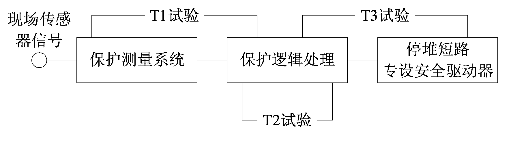
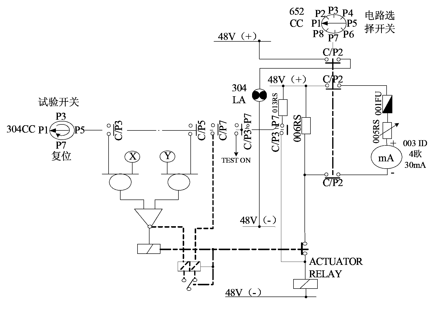
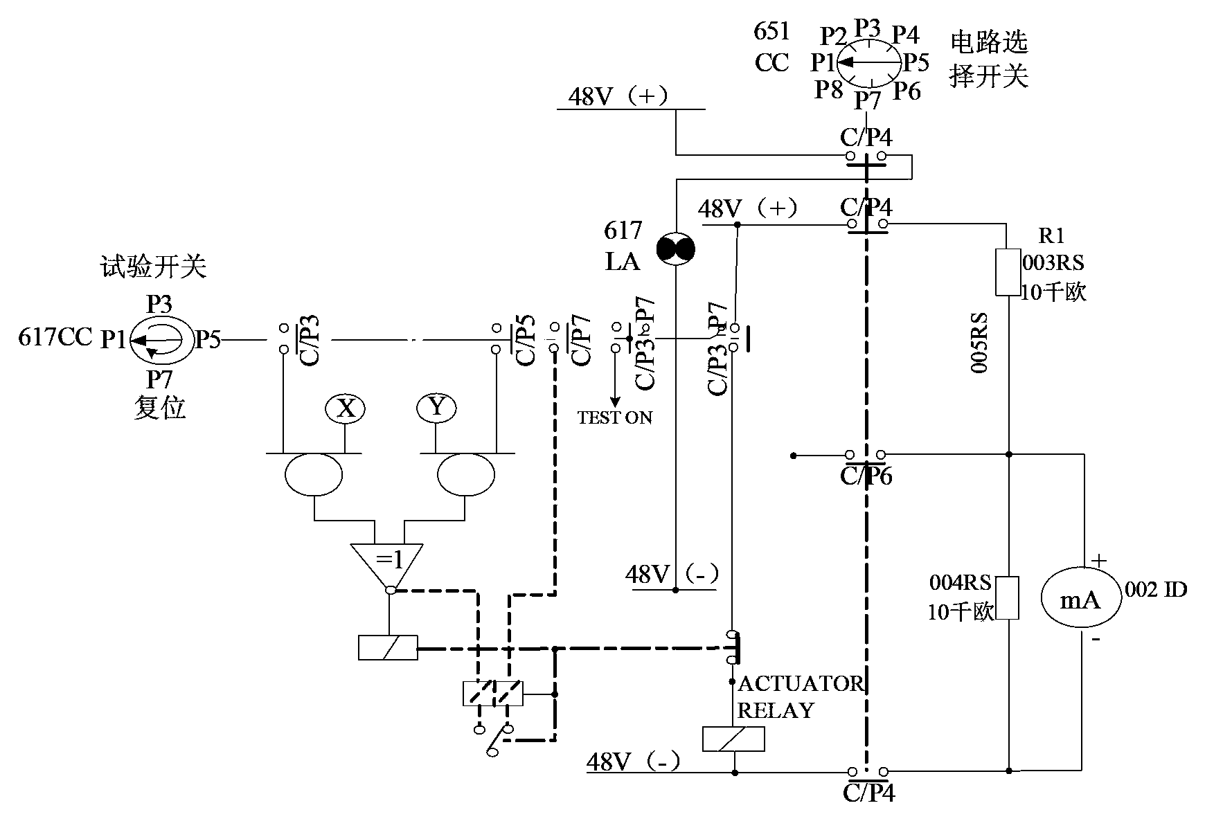
[0058] The T3 test circuit of the nuclear power plant RPR system of this embodiment adopts a parallel resistance inspection current circuit, and the circuit includes a plurality of test switches, and each test switch contains multiple pairs of switch contacts, wherein at least one test switch corresponds to multiple devices, the embodiment is for The optimization of the T3 test circuit is: at least two pairs of contacts in at least one test switch are connected in parallel to form a parallel connection point, and the output of the parallel connection point drives the test circuit. When there is a problem with one pair of contact points, the other pair of contact points can guarantee normal operation, thereby improving the reliability of the test circuit and reducing the risk of equipment malfunction due to contact failure of the T3 test switch during the test.

Embodiment 2

[0060] In this embodiment, on the basis of Embodiment 1, the output of the parallel connection point is used to drive the nuclear-level relay. The nuclear-level relay refers to a special relay for nuclear power plants, which may be existing in the RPR system or newly added. By connecting the contacts of nuclear grade relays to the test circuit, the reliability of the equipment can be further improved.

Embodiment 3

[0062] In this embodiment, on the basis of Embodiment 2, the normally open contact of the nuclear-level relay controlled by the parallel connection point is injected into the single logic branch of the circuit, and the disconnection of the normally open contact is judged, so that when When the normally open contact fails, the test signal is blocked to prevent the equipment from malfunctioning during the test.


PUM


Abstract

The application discloses a T3 test loop of a reactor protection system in a nuclear power station and an optimization method thereof. In the optimization method, the T3 test loop employs parallel resistance to check current loop, and comprises a plurality of test switches, wherein at least one test switch is corresponding to a multiple paths of devices, and the at least one test switch has at least two pairs of contact in parallel connection to form parallel contacts. The application has the beneficial effects that: at least two pairs of contact in the test switches are in parallel output to drive the test loop and reduce the risk of maloperation caused by high failure rate of contacts; in one embodiment, nuclear grade relay nodes are connected into the test loop to further improve the reliability of the equipment; in another embodiment, self-locking of test signal is added for interlocking test signal in the case of switch contact failure to reduce the maloperation; and in another embodiment, additional alarm signal sent to a main control enables the normal operation and monitoring on the loop, in order to reduce the risk of refusal-operation caused by scheme optimization.

Description

technical field [0001] This application relates to nuclear radiation safety and monitoring technology, in particular to a T3 test circuit of a nuclear power plant reactor protection system and an optimization method thereof. Background technique [0002] A nuclear power plant is a power plant that uses the energy released by nuclear fission (Nuclear Fission) or nuclear fusion (Nuclear Fusion) reactions to generate electricity. [0003] In order to protect the health of the staff of the nuclear power plant and the residents around the nuclear power plant, the design, construction and operation of the nuclear power plant adopt the principle of defense in depth, providing multiple protections in terms of equipment and measures to ensure that the nuclear power plant can effectively control the output power of the reactor; and can In the event of various natural disasters, such as earthquakes, tsunamis, floods, etc., or man-made fires, explosions, etc., it can also ensure suffici...

Claims


Application Information

Patent Timeline
IPC IPC(8): G21C17/00
CPCY02E30/30
Inventor 黄文郁刘新东彭超崔国华季涛
Owner CHINA GENERAL NUCLEAR POWER CORP
Why Eureka
Try Eureka