A method for separating insulation layers of electromagnetic wires

A separation method and electromagnet wire technology, applied in the direction of dismantling/armoring cable equipment, etc., can solve the problems of large power, long time, easy to pollute the environment, etc., and achieve the effect of reasonable design, easy replacement and simple device structure

Active Publication Date: 2016-07-13
株洲兆源机电科技有限公司
View PDF26 Cites 0 Cited by
  • Summary
  • Abstract
  • Description
  • Claims
  • Application Information

AI Technical Summary

Problems solved by technology

The disadvantage is that the chemical reaction to remove the insulating layer is slow and takes a long time, which is not suitable for mass production line applications. The time for removing the insulating layer is not suitable for control. If the processing time is too long, the wires will often be oxidized
The price of the solvent is high, the disposal of the solution is difficult, and it is easy to pollute the environment
[0005] Based on the fact that the current process for separating the insulating layer of electromagnetic wires is complex, requires high equipment, needs to provide greater power, consumes a lot of energy, and is easy to pollute the environment, there is an urgent need for a more advanced method and method for separating the insulating layer of electromagnetic wires. device to meet the demand for recycling metal wires of magnet wires

Method used


Image

  • A method for separating insulation layers of electromagnetic wires

Examples


Embodiment 1

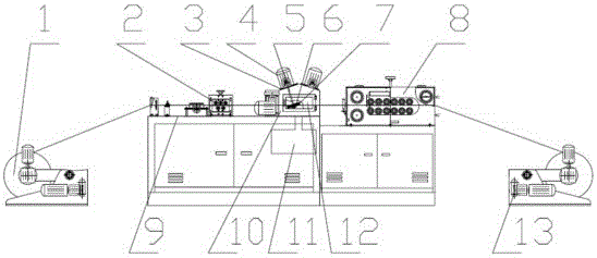
[0072] A device for separating the insulating layer of electromagnetic wires. When working, the straightening device 2, the stripping mechanism, the dust collecting device 11 and the traction mechanism 8 are fixed on the platform 9, the wire releasing mechanism 1 is placed in front of the platform 9, and the wire take-up mechanism 13 is placed on the After platform 9. Putting in the magnet wire is thin film burning copper flat wire. The straightening device includes a horizontal straightening wheel set and a vertical straightening wheel set, and the gap between the wheel sets is adjusted so that the straightening wheels are close to the copper wire for straightening. Stripping mechanism comprises stripping box 10, guide rail 3, motor 4, metal rod 5, stripping wheel 6, bolt 7 and transparent baffle 12, can observe the situation inside the stripping mechanism by transparent baffle 12. Each stripping wheel 6 is connected with a motor 4 by a metal rod 5, and the rotation of the m...

Embodiment 2

[0074] A device for separating the insulating layer of electromagnetic wires. When working, the straightening device 2, the stripping mechanism, the dust collecting device 11 and the traction mechanism 8 are fixed on the platform 9, the wire releasing mechanism 1 is placed in front of the platform 9, and the wire taking mechanism 13 Placed behind platform 9. Put in the magnet wire as an enamelled copper round wire. The straightening device 2 includes a horizontal straightening wheel set and a vertical straightening wheel set, and the gap between the wheel sets is adjusted so that the straightening wheels are close to the copper wires to perform straightening. Stripping mechanism comprises stripping box 10, guide rail 3, motor 4, metal bar 5 stripping wheels 6, bolt 7 and transparent baffle 12, can observe the situation inside the stripping mechanism by transparent baffle 12. Each stripping wheel 6 is connected with a motor 4 by a metal rod 5, and the rotation of the motor 4 d...

Embodiment 3

[0076] A device for separating the insulating layer of electromagnetic wires. When working, the straightening device 2, the stripping mechanism, the dust collecting device 11 and the traction mechanism 8 are fixed on the platform 9, the wire releasing mechanism 1 is placed in front of the platform 9, and the wire taking mechanism 13 Placed behind platform 9. Put in the magnet wire as wire-clad copper square wire. The straightening device 2 includes a horizontal straightening wheel set and a vertical straightening wheel set, and the gap between the wheel sets is adjusted so that the straightening wheels are close to the copper wires to perform straightening. The peeling mechanism comprises a peeling box, a guide rail 3, a motor 4, a metal rod 5, a peeling wheel 6, a bolt 7 and a transparent baffle 12, through which the internal situation of the peeling mechanism can be observed. Each stripping wheel 6 is connected with a motor 4 by a metal rod 5, and the rotation of the motor ...


PUM


Abstract

The invention discloses an electromagnetic wire insulating layer separation device and method. The electromagnetic wire insulating layer separation device comprises a paying-off mechanism, a stripping mechanism, a taking-up mechanism, a straightening device, a traction mechanism, a platform and a dust collection device. The platform is located between the paying-off mechanism and the taking-up mechanism. The straightening device, the stripping mechanism, the dust collection device and the traction mechanism are all arranged on the platform. The stripping mechanism comprises a stripping box, a guide rail, motors, a metal rod, stripping wheels and a transparent baffle. According to the electromagnetic wire insulating layer separation method, an electromagnetic wire is straightened, the guide rail is adjusted so that all the stripping wheels can be attached to the surface of the electromagnetic wire, and the motors rotate to drive the stripping wheels to rotate so that an insulating layer of the electromagnetic wire can be stripped off. The electromagnetic wire insulating layer separation device has the advantages of being simple in structure, reasonable in design, reliable in performance, capable of separating the electromagnetic wire insulating layer through the coordination effect of all components, free of increased power, low in energy consumption, not prone to environment pollution, and capable of meeting the requirement for recycling of metal wires of electromagnetic wires.

Description

technical field [0001] The invention relates to the technical field of recycling metal wires, in particular to a method for separating insulating layers of electromagnetic wires. Background technique [0002] Electromagnetic wire is a metal wire with an insulating layer, which is used to realize the mutual conversion of electric energy and magnetic energy, so it is also called winding wire. Electromagnetic wire can not only meet the requirements of stretching, bending and abrasion during the manufacturing process, swelling and erosion during the process of dipping and drying, but also meet the requirements of long-term work at high temperature and withstand certain conditions during use. Strong vibration in the occasion and centrifugal force at high speed, corona and breakdown resistance under high voltage, and chemical corrosion resistance under special atmosphere. Therefore, it is difficult to separate the insulating layer of the magnet wire from the metal wire. [0003]...

Claims


Application Information

Patent Timeline
Patent Type & Authority Patents(China)
IPC IPC(8): H02G1/12
Inventor 王一靓李海红李强张步峰魏基强罗艳芝兰玉文钱海建唐创业姚颖
Owner 株洲兆源机电科技有限公司
Why Eureka
Try Eureka