
Envelope tracking radio frequency power amplifier

A radio frequency power and envelope tracking technology, applied in power amplifiers, high-frequency amplifiers, etc., can solve the problems of reduced conversion efficiency and difficult design, and achieve the effect of easy circuit and optimized efficiency

Inactive Publication Date: 2014-05-14
ZHEJIANG UNIV
View PDF4 Cites 26 Cited by
  • Summary
  • Abstract
  • Description
  • Claims
  • Application Information

AI Technical Summary

Problems solved by technology

[0004] In the existing envelope tracking technology, the DC-DC converter is commonly used as the power supply bias of the RF power amplifier, but the main defect of the existing technical solution is: the envelope curve of the third-generation wireless communication system and the fourth-generation wireless communication system The maximum signal bandwidth can reach more than 20MHz, and the conversion frequency of the required DC-DC converter must be at a very high frequency, and its frequency will reach more than tens of MHz. design, on the other hand, when it works at a very high frequency, its conversion efficiency will be reduced, resulting in redundant power consumption

Method used


Image

  • Envelope tracking radio frequency power amplifier
  • Envelope tracking radio frequency power amplifier
  • Envelope tracking radio frequency power amplifier

Examples


Embodiment Construction

[0024] The technical solutions of the present invention will be further described below in conjunction with the accompanying drawings and embodiments.

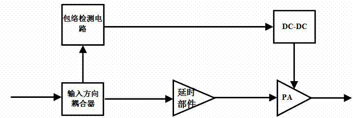
[0025] figure 1 Shown is a schematic diagram of the structure of a commonly used envelope tracking RF power amplifier. It works as follows:

[0026] frf ( t ) is the signal to be transmitted by the power amplifier, which is divided into two signals by the input directional coupler, frf 1 ( t )and frf 2 (t), where frf 1 ( t ) contains the signal to emit frf ( t ) for most of the power, frf 2 ( t ) through the input directional coupler, containing frf ( t ) signal information, which is mainly to provide an envelope signal for the envelope signal detection circuit of the subsequent stage;

[0027] envelope detection circuit from the signal frf 2 ( t ) to separate the envelope signal E ( t );

[0028] DC-DC converter according to the envelope signal E ( t ) modulates the supply voltage to generate...


PUM


Abstract

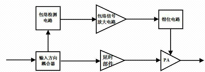
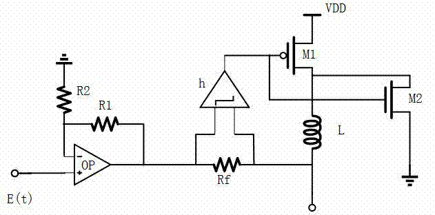
The invention provides an envelope tracking radio frequency power amplifier which comprises an input direction coupler, an envelope signal detection circuit, an envelope signal amplifier, a delay component, a clamping circuit and a radio frequency power amplifier body. Input signals are divided into two parts through the input direction coupler; one part of input signals pass through the envelope signal detection circuit, the envelope signal amplifier and the clamping circuit and then provide bias for the radio frequency power amplifier body; the other part of input signals pass through the delay component, so that the bias voltage of the radio frequency power amplifier body and the input signals are completely synchronous; finally, real-time envelope tracking is achieved. The envelope signal amplifier amplifies the envelope signals, so that the envelope signals are large enough to provide bias for the radio frequency power amplifier body. The clamping circuit limits the amplitude value of the amplified signals amplified by the envelope signal amplifier, and reduces the distortion of the envelope tracking radio frequency power amplifier. All the components of the envelope tracking radio frequency power amplifier can be designed to work at wide frequency, and can meet multiple wireless communication standards.

Description

technical field [0001] The invention relates to the field of mobile phone communication, in particular to an envelope tracking radio frequency power amplifier. Background technique [0002] With the development and promotion of the third-generation wireless communication system and the fourth-generation wireless communication system, the power consumption of mobile terminals has attracted more and more attention in the industry, and mobile terminals with low power consumption have become a hot research topic in the industry. [0003] In order to improve the transmission efficiency of the power amplifier, non-constant envelope modulation is used in the communication system for signal modulation. At present, in order to effectively solve the contradiction between the efficiency and the linearity of the radio frequency power amplifier, the industry usually adopts the envelope tracking technology. [0004] In the existing envelope tracking technology, the DC-DC converter is com...

Claims


Application Information

Patent Timeline
IPC IPC(8): H03F3/20H03F3/189
Inventor 王伟印韩雁
Owner ZHEJIANG UNIV
Learn More