Frequency offset tracking and compensating method and device

A compensation method and technology of a compensation device, which are applied in the directions of digital transmission systems, baseband system components, and error prevention, can solve the problems of expanding the range of frequency offset tracking, affecting the accuracy of frequency offset estimation, and small amount of calculation, and achieving extended frequency The ability of partial estimation and tracking, the effect of simple implementation method, and cost-effective

Active Publication Date: 2014-05-14
SPREADTRUM COMM (TIANJIN) INC
View PDF4 Cites 8 Cited by
  • Summary
  • Abstract
  • Description
  • Claims
  • Application Information

AI Technical Summary

Problems solved by technology

[0003] In some communication systems, such as Time Division-Synchronous Code Division Multiple Access (TD-SCDMA, Time Division-Synchronous Code Division Multiple Access) communication systems, the commonly used frequency offset estimation and tracking method is to use several symbols close to the training sequence for frequency Offset estimation is simple and easy to implement, with a small amount of calculation, and the tracking effect is good, but due to the limitation of accuracy, it cannot estimate large frequency offsets (those skilled in the art know that frequency offsets above 1000 Hz can usually be considered as large frequency offsets)
In the prior art, although some technical solutions for frequency offset tracking and compensation can expand the range of frequency offset estimation to a certain extent, they need to change the length of data used, which affects the accuracy of frequency offset estimation, or the algorithm is improved. Additional calculations are required, which increases the amount of calculations, and it is difficult to simply and effectively expand the range of frequency offset tracking to effectively deal with large frequency offsets, especially in the case of large-scale jumps in frequency offsets generated in high-speed mobile environments

Method used


Image

  • Frequency offset tracking and compensating method and device
  • Frequency offset tracking and compensating method and device
  • Frequency offset tracking and compensating method and device

Examples


Embodiment 1

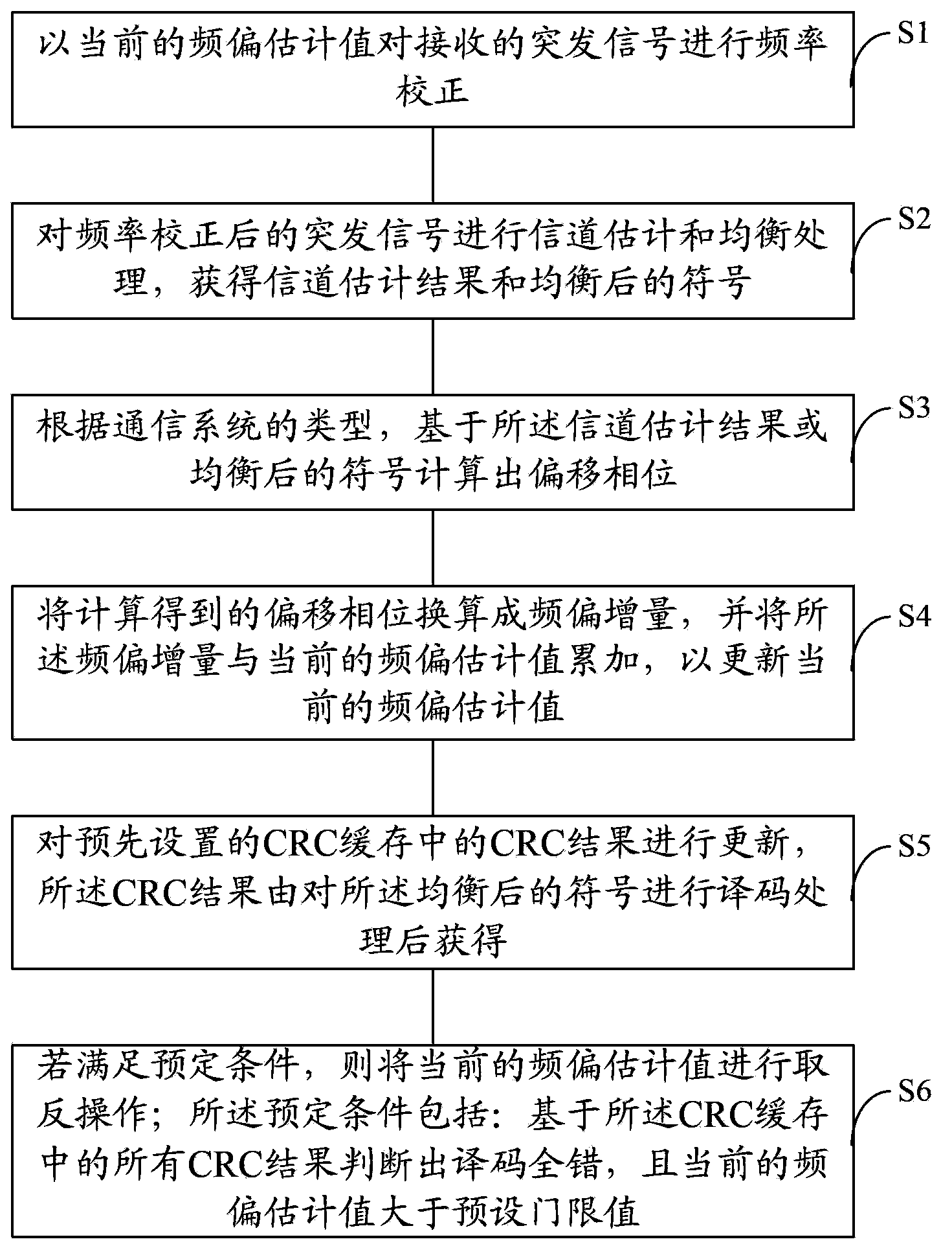
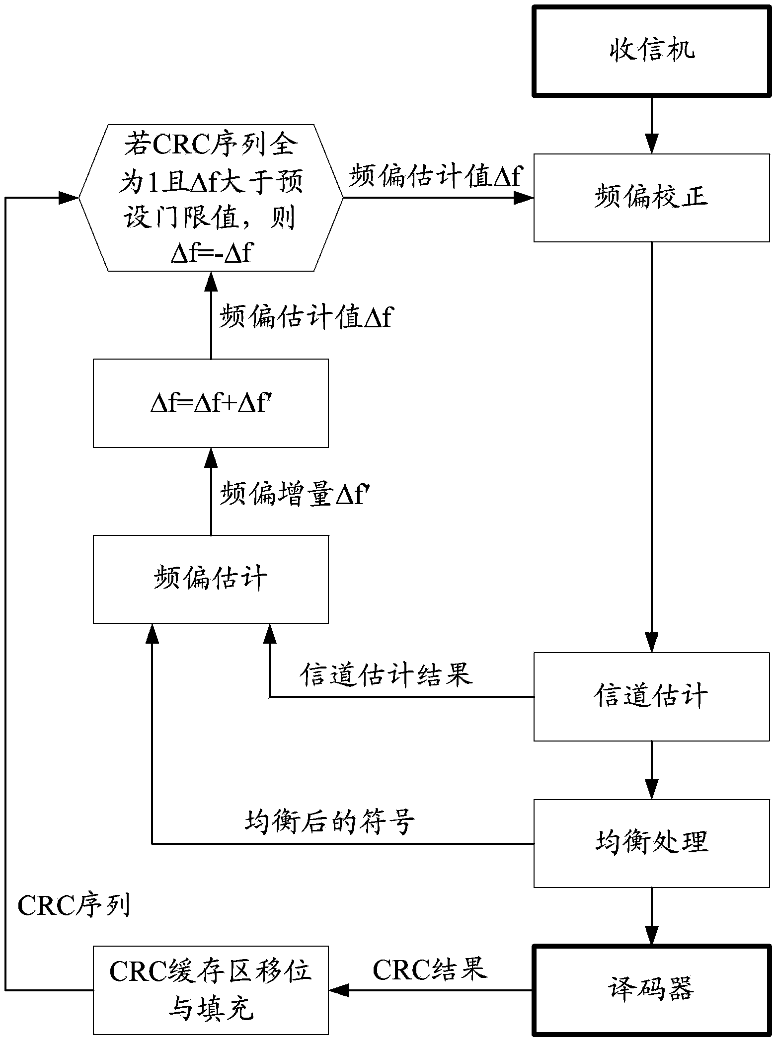
[0068] image 3 It is a flow chart of burst signal processing with frequency offset tracking and compensation in Embodiment 1 of the present invention. Combine below figure 2 with image 3 The frequency offset tracking and compensation method in this embodiment will be described in detail.

[0069] Firstly, the initialization operation is performed: the initial value of the estimated frequency offset value Δf is set to 0; a storage space is opened as a CRC buffer with a length of M. In this embodiment, the length M of the CRC cache is determined based on the need for stability of the communication system. For example, if the need for stability of the communication system is greater, the value of M can be set to be larger. In this embodiment, M can be set to 8 or a value greater than 8, and the CRC buffer is initialized to 0.

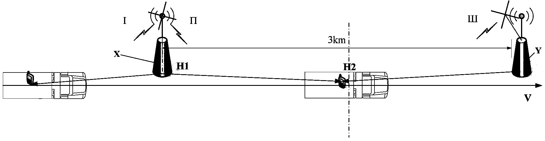
[0070] When the receiver receives the signal from the wireless port, after frequency conversion and filtering, a burst signal r(i) in complex form ...

Embodiment 2

[0108] The difference from Embodiment 1 is that in this embodiment, the process of judging and processing the possible large frequency deviation or frequency deviation hopping (that is, step S6) is placed in the burst signal processing flow At the front end, if the frequency offset estimation value is inverted after step S6 is performed, the frequency offset estimation value obtained after the inversion operation can be used as the "current frequency offset estimation value" for the current burst signal frequency offset correction.

[0109] Figure 4 It is a flow chart of burst signal processing with frequency offset tracking and compensation in Embodiment 2 of the present invention. Combine below figure 2 with Figure 4 A brief description will be given of the frequency offset tracking and compensation method in this embodiment.

[0110] Firstly, the initialization operation is still performed, and reference may be made to the relevant description in Embodiment 1, which ...

Embodiment 3

[0120] Corresponding to the frequency offset tracking and compensation method described in the first embodiment, this embodiment provides a frequency offset tracking and compensation device. Figure 5 is a schematic structural diagram of a frequency offset tracking and compensation device according to Embodiment 3 of the present invention, as shown in Figure 5 As shown, the frequency offset tracking and compensation device includes: a frequency offset correction unit 1, adapted to perform frequency correction on the received burst signal with the current frequency offset estimated value; a channel estimation and equalization processing unit 2, adapted to frequency The corrected burst signal is subjected to channel estimation and equalization processing to obtain channel estimation results and equalized symbols; the offset phase determination unit 3 is adapted to calculate based on the channel estimation results or equalized symbols according to the type of communication system...


PUM


Abstract

The invention relates to a frequency offset tracking and compensating method and device. The method includes: performing frequency correction on a received burst signal with a current frequency offset estimated value; performing channel estimation and equalization processing on the burst signal after frequency correction, and obtaining a channel estimation result and an equalized symbol; calculating an offset phase position based on the channel estimation result or the equalized symbol; converting the offset phase position to a frequency offset increment, and accumulating the frequency offset increment and the current frequency offset estimated value to update the current frequency offset estimated value; updating a CRC result in a preset CRC buffer memory, and CRC result being obtained by performing decoding processing on the equalized symbol; and if predetermined conditions are satisfied, performing negation operation on the current frequency offset estimated value, and the predetermined conditions including that totally wrong decoding is judged based on all CRC results in the CRC buffer memory, and the current frequency offset estimated value is greater than a preset threshold value. The technical scheme can easily and effectively expand a frequency offset tracking range, so as to deal with large frequency offset or a frequency offset jump.

Description

technical field [0001] The invention relates to the field of communication technology, in particular to a frequency offset tracking and compensation method and device. Background technique [0002] With the increase of railway speed, Doppler frequency deviation becomes an important problem in mobile communication. The private railway network is closely arranged and densely arranged along the railway track, and mobile terminals frequently switch cells along the train as the train is running, and the Doppler frequency offset jumps become more frequent. Such as figure 1 As shown, assuming that the high-speed train is moving forward at a speed V (for example, V=200, 250, 300 or 350 km / h), and the distance between two adjacent base stations X and Y on the driving route is 3 km, points H1 and H2 will be The driving area where the two base stations are located is divided into three areas: I, Π, and Ш. When passing through base station X (point H1), there will be a frequency offse...

Claims


Application Information

Patent Timeline
IPC IPC(8): H04L25/02H04L25/03H04L1/00
Inventor 周用芳刘文明董霄剑
Owner SPREADTRUM COMM (TIANJIN) INC
Why Eureka
Try Eureka