Supercharge Your Innovation With Domain-Expert AI Agents!

Heat collecting end

A heat collection end and storage cavity technology, applied in cooling/ventilation/heating transformation, etc., can solve the problems of no essential improvement in heat dissipation level, large pressure drop in microchannels, and small flow heat transfer, and achieve large flow and low flow. The effect of resistance, high heat dissipation capacity

Inactive Publication Date: 2014-05-14
TSINGHUA UNIV
View PDF8 Cites 1 Cited by
  • Summary
  • Abstract
  • Description
  • Claims
  • Application Information

AI Technical Summary

Problems solved by technology

However, the microchannel pressure drop of the existing cooling device is large, and the convective heat transfer of the fluid passing through the device to be cooled is very small, so the heat dissipation level has not been substantially improved.

Method used


Image

  • Heat collecting end
  • Heat collecting end
  • Heat collecting end

Examples


Embodiment Construction

[0017] The heat collecting end provided by the present invention will be further described in detail below in conjunction with the accompanying drawings and specific embodiments.

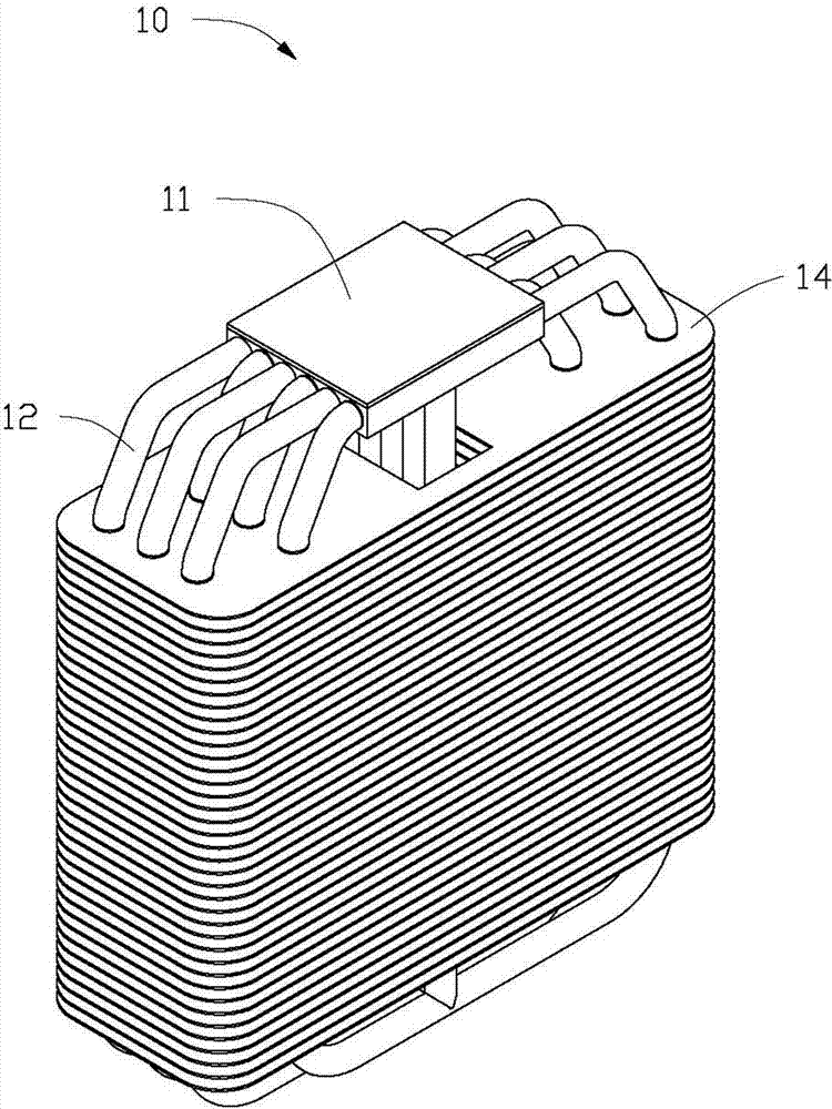
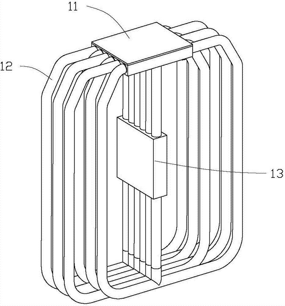
[0018] see figure 1 and figure 2 , the embodiment of the present invention provides a heat dissipation device 10, the heat dissipation device 10 can be used for heat dissipation of computer chips, optoelectronic devices and the like.

[0019] The heat dissipation device 10 includes a heat collecting end 11 , a circulation line 12 , a pump 13 , a cooling fin 14 and a working medium (not shown) at least provided on the heat collecting end 11 , the circulation line 12 or the electromagnetic pump 13 . The working medium is low melting point metal or low melting point alloy. The heat collecting end 11 and the electromagnetic pump 13 are connected to form a closed passage through the circulation pipeline 12 , and the cooling fins 14 are arranged on the outer wall of the circulation pipeline 12 for diss...


PUM

PropertyMeasurementUnit
Apertureaaaaaaaaaa

Abstract

The invention relates to a heat collecting end which comprises a box body and a micro-channel module. The box body is provided with a containing cavity. The two opposite sides of the box body are provided with holes respectively, wherein the holes serve as outlets of the heat collecting end. The bottom of the box body is provided with holes which serve as inlets of the heat collecting end. The micro-channel module is provided with a plurality of cylindrical holes for working media to pass through. The middle of the micro-channel module is provided with a wedge-shaped groove which serves as an inlet of the micro-channel module, and the micro-channel module is fixedly arranged in the containing cavity of the box body. The inlet of the micro-channel module is arranged by being right opposite to the inlet of the heat collecting end. The cylindrical holes of the micro-channel module extend towards the outlets in the other side of the heat collecting end from the outlets in one side of the heat collecting end.

Description

technical field [0001] The invention relates to a heat collection end, in particular to a heat collection end using a lotus-shaped porous material. Background technique [0002] In recent years, the thermal barrier problem caused by high integration has become one of the important problems and technical bottlenecks restricting the development of computer chips and optoelectronic devices. How to efficiently and safely dissipate heat from chips has become one of the important topics in the research of electronic devices. . [0003] The general principle of heat dissipation design is to provide a thermal resistance path as low as possible between the device to be dissipated and the environment. The purpose is to control the core temperature and make it work within the allowable temperature range. After years of development, single-phase fluid circuit heat dissipation technology has been widely used in the field of heat dissipation due to its large heat dissipation and convenie...

Claims


Application Information

Patent Timeline
IPC IPC(8): H05K7/20
Inventor 刘源励精图治李言祥吴健卓伟佳
Owner TSINGHUA UNIV
Features
  • R&D
  • Intellectual Property
  • Life Sciences
  • Materials
  • Tech Scout
  • Unparalleled Data Quality
  • Higher Quality Content
  • 60% Fewer Hallucinations
Learn More