Antenna device and electronic device

An antenna device and antenna coil technology, which is applied to the antenna grounding device, antenna, antenna parts and other directions, can solve the problem of inability to communicate

Active Publication Date: 2014-05-14
MURATA MFG CO LTD
View PDF3 Cites 16 Cited by
  • Summary
  • Abstract
  • Description
  • Claims
  • Application Information

AI Technical Summary

Problems solved by technology

[0003] When such an antenna for non-contact communication is mounted on the back surface of a metal member, the magnetic field is shielded by the metal member, so it cannot communicate with a reader, etc. located on the opposite side of the metal member from the antenna.

Method used


Image

  • Antenna device and electronic device
  • Antenna device and electronic device
  • Antenna device and electronic device

Examples


no. 1 Embodiment approach 》

[0050] refer to Figure 1 ~ Figure 4 The antenna device 101 according to the first embodiment will be described.

[0051] figure 1 (A) is a plan view of the antenna device 101 according to the first embodiment, figure 1 (B) is figure 1 (A) Cross-sectional view of part X-X. exist figure 1 (A), figure 1 (B) shows only the structure of the main part.

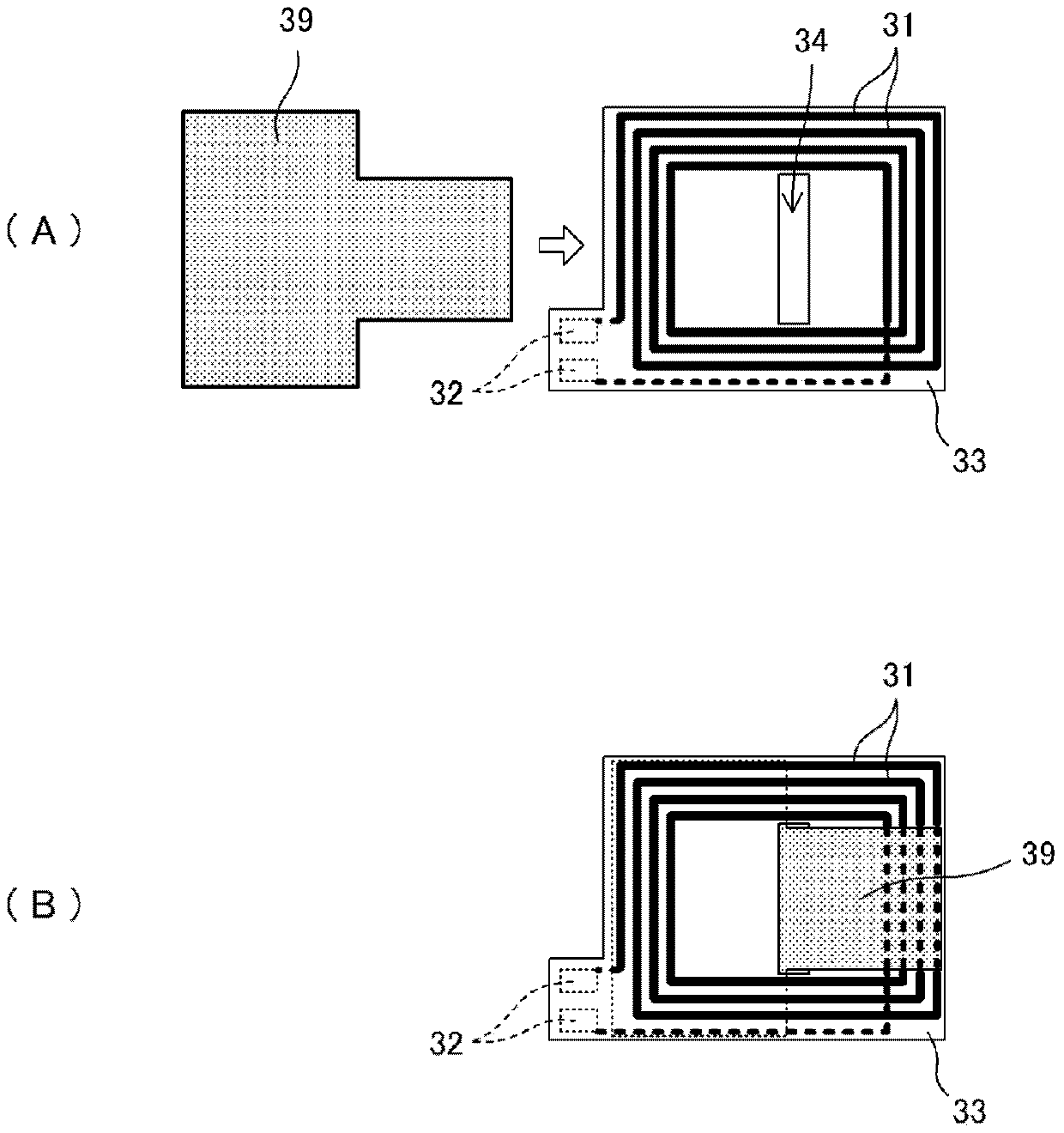
[0052] figure 2(A) is a plan view of the flexible base material 33 and the magnetic core 39 on which the antenna coil 31 is formed, figure 2 (B) is a top view of the state where the magnetic core 39 is combined with the flexible base material 33 .

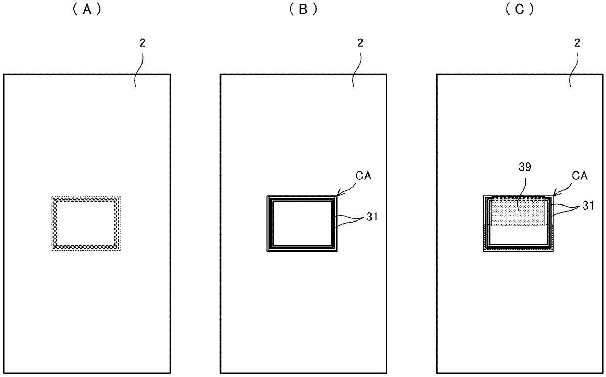
[0053] This antenna device 101 includes an antenna coil 31 , a magnetic core 39 , and a metal member 2 . The antenna coil 31 is formed on a flexible base material 33 . The antenna coil 31 is wound in a ring shape or a helical shape along the magnetic core 39 with the winding center portion serving as a coil opening, and both ends are taken out as connecting portions 32 ...

no. 2 Embodiment approach 》

[0074] refer to Figure 5 ~ Figure 7 The antenna device 102 according to the second embodiment will be described.

[0075] Figure 5 (A) is a plan view of the antenna device 102 according to the second embodiment, Figure 5 (B) is Figure 5 (A) Cross-sectional view of part X-X. But when Figure 5 (A), Figure 5 In (B), only the structure of the main part is shown.

[0076] This antenna device 102 includes an antenna coil 31 , a magnetic core 39 and a metal member 2 . The antenna coil 31 is formed on a flexible base material 33 . The antenna coil 31 is wound in a ring shape or a helical shape with the winding center portion serving as a coil opening.

[0077] The structures of the antenna coil 31, the magnetic core 39, and the metal member 2 are the same as those shown in the first embodiment. The difference is the positions of the antenna coil 31 and the magnetic core 39 with respect to the opening CA of the metal member 2 . In the second embodiment, the antenna coil...

no. 3 Embodiment approach 》

[0092] refer to Figure 8 ~ Figure 11 An antenna device according to a third embodiment will be described.

[0093] Figure 8 (A) is a plan view of the antenna device 103X according to the third embodiment, Figure 8 (B) is Figure 8 (A) Cross-sectional view of part X-X. Figure 9 (A) is a plan view of another antenna device 103Y according to the third embodiment, Figure 9 (B) is Figure 9 (A) Cross-sectional view of part X-X.

[0094] Figure 8 (A), Figure 8 The antenna device 103X shown in (B) and Figure 5 The antenna arrangement 102 shown differs in the shape of the magnetic core 39 . In the third embodiment, the magnetic core also extends from the outer edge of the portion of the antenna coil that is closer to the metal member 2 than the magnetic core 39 (the surface-side coil conductor 31A) to the inner edge of the opening CA of the metal member 2. 39.

[0095] Figure 9 (A), Figure 9 In the antenna device 103Y shown in (B), the antenna coil 31 and the magn...


PUM


Abstract

An antenna device (101) is provided with an antenna coil (31), a magnetic core (39), and a metal member (2). The antenna coil (31) is formed into a flexible substrate (33). The antenna coil (31) is wound in a loop shape or a spiral shape where the center part of the winding is the coil opening. The magnetic core (39) is inserted through a slit-shaped opening of the flexible substrate (33). A rectangular opening (CA) is formed in the metal member (2), and the antenna coil (31) is exposed through the opening (CA) of the metal member (2). A coil conductor (31A) on the surface side is on the opening (CA) side away from the magnetic core (39), and the magnetic flux phia interlinks with the coil conductor (31A) on the surface side.

Description

technical field [0001] The present invention relates to an RFID system that communicates with a target device through an electromagnetic field signal, an antenna device used in a short-range wireless communication system, and an electronic device including the antenna device. Background technique [0002] In recent years, in non-contact communication systems such as RFID systems and short-range wireless communication systems that have been increasingly used, in order to communicate between portable electronic devices such as mobile phones or between portable electronic devices and readers, each device An antenna for communication is mounted on it. [0003] When such an antenna for non-contact communication is mounted on the back surface of a metal member, the magnetic field is shielded by the metal member, so it cannot communicate with a reader / writer or the like located on the opposite side of the metal member from the antenna. [0004] On the other hand, Patent Document 1...

Claims


Application Information

Patent Timeline
Patent Type & Authority Applications(China)
IPC IPC(8): H01Q7/06G06K19/07
CPCH01Q1/2216H01Q1/38H01Q7/06G06K19/07771H01Q1/48
Inventor 伊藤宏充
Owner MURATA MFG CO LTD
Why Eureka
Try Eureka