
X-ray out-of-phase pulse dual-plane synchronous real-time imaging device and imaging method

A real-time imaging, dual-plane technology, applied in medical science, equipment for radiological diagnosis, diagnosis, etc., can solve the problems of not being able to display images from two angles synchronously in real time, two-way X-ray interference, etc.

Active Publication Date: 2017-07-18
BEIJING EAST WHALE IMAGE TECH
View PDF2 Cites 0 Cited by
  • Summary
  • Abstract
  • Description
  • Claims
  • Application Information

AI Technical Summary

Problems solved by technology

This method solves the problem of two-way X-ray interference scattering, but it cannot display images from two angles simultaneously in real time

Method used


Image

  • X-ray out-of-phase pulse dual-plane synchronous real-time imaging device and imaging method
  • X-ray out-of-phase pulse dual-plane synchronous real-time imaging device and imaging method
  • X-ray out-of-phase pulse dual-plane synchronous real-time imaging device and imaging method

Examples


Embodiment 1

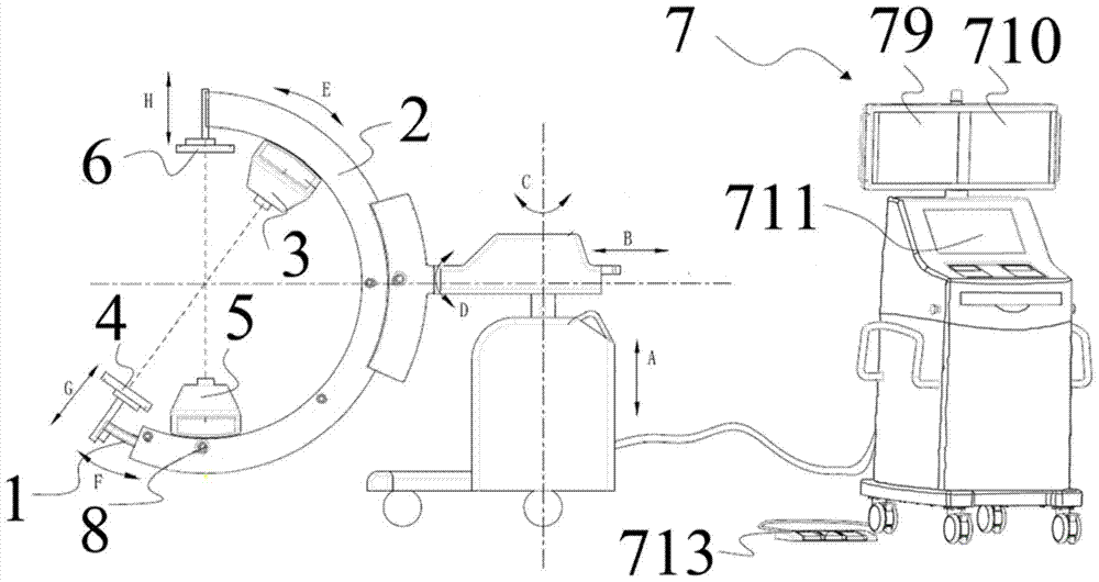
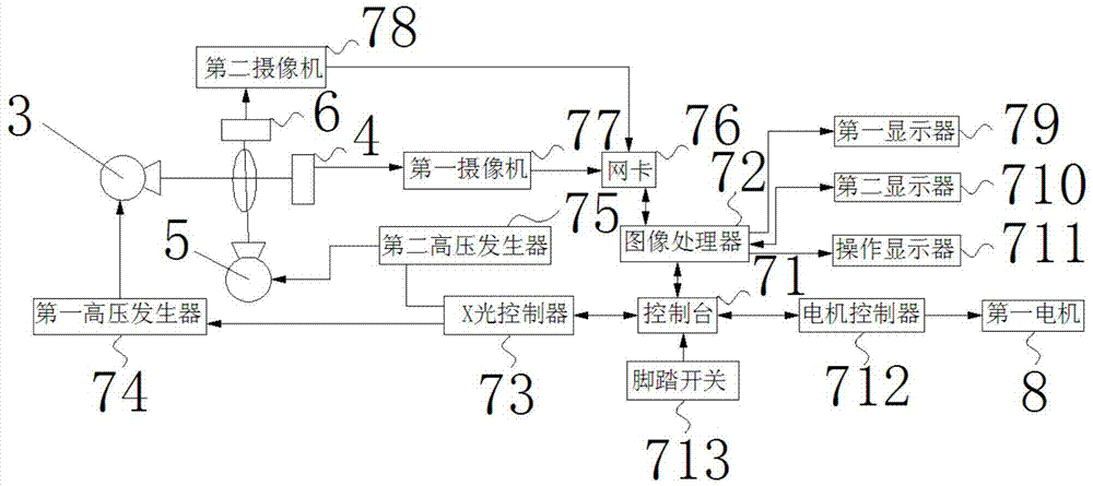
[0045] refer to Figure 1-4 , this embodiment provides an X-ray out-of-phase pulse dual-plane synchronous real-time imaging device, including a first C-arm 1, a second C-arm 2, a support device, a first X-ray generating device 3, a first image receiving Device 4, second X-ray generating device 5, second image receiving device 6 and imaging control device 7;

[0046] The first C-shaped arm 1 is slidably arranged on the second C-shaped arm 2, and the second C-shaped arm 2 is slidably arranged on the support device;

[0047] The first X-ray generating device 3 and the first image receiving device 4 are respectively fixed on both ends of the first C-shaped arm 1 along the circumferential direction;

[0048] The second X-ray generating device 5 and the second image receiving device 6 are respectively fixed on two ends of the second C-shaped arm 2 along the circumferential direction;

[0049] The intersection of the X-ray emitting plane of the first X-ray generating device 3 and the...

Embodiment 2

[0060] refer to Figure 1-4 , the present embodiment provides a method for realizing X-ray out-of-phase pulse biplane synchronous real-time imaging device using the described X-ray out-of-phase pulse biplane synchronous real-time imaging device, comprising the following steps:

[0061] S10. Control the movement of the first motor 8 so that the included angle between the X-ray direction emitted by the first X-ray generating device 3 and the X-ray direction emitted by the second X-ray generating device 5 is a preset set value;

[0062] S20. Select the working mode of the X-ray out-of-phase pulse biplane synchronous real-time imaging device;

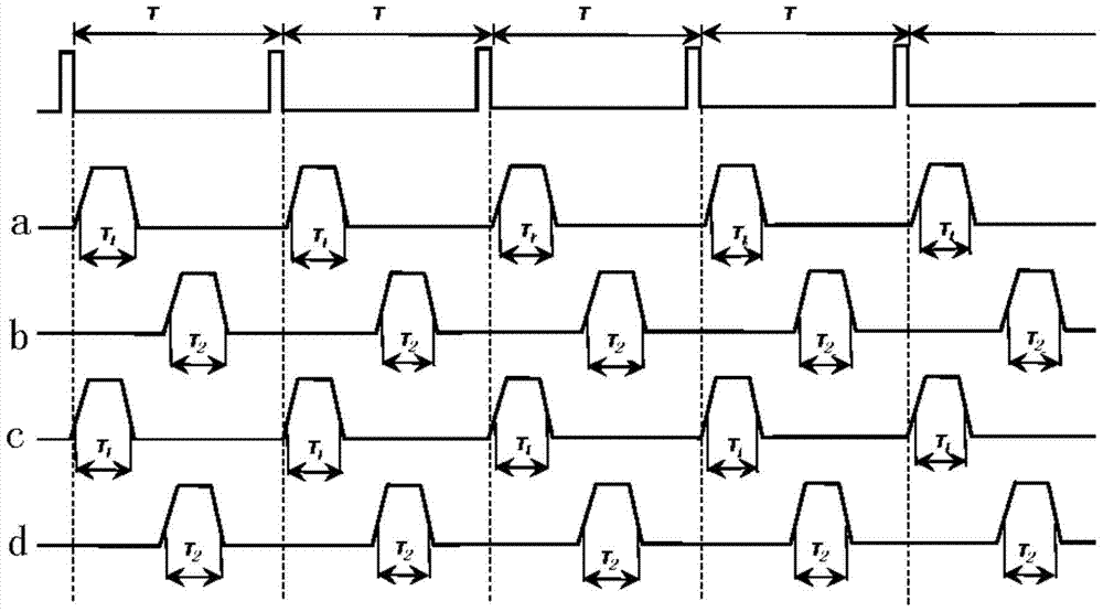
[0063] S30. The X-ray controller 73 controls the first high-voltage generator 74 and the second high-voltage generator 75 to generate pulsed high voltages, while the pulsed high voltages of the first high-voltage generator 74 and the second high-voltage generator 75 respectively make The X-ray pulses generated by the first X-ray generator...


PUM


Abstract

The invention discloses an X-ray out-of-phase pulse dual-plane synchronous real-time imaging device and an imaging method. The X-ray out-of-phase pulse dual-plane synchronous real-time imaging device includes a second C-shaped arm and is slidably arranged on the second The first C-shaped arm on the C-shaped arm, the first X-ray generating device and the first image receiving device are installed on the first C-shaped arm, and the second X-ray generating device and the second image receiving device are installed on the On the second C-arm, the imaging control device controls the period and pulse width of the first X-ray pulse and the second X-ray pulse, so that the first X-ray pulse and the second X-ray pulse do not interfere or interfere with each other The accuracy is low, so that the first imaging device and the second imaging device can be synchronized and generate X-ray images in real time. Further, the imaging control device performs synchronization by processing the X-ray images and displays them in real time. The X-ray image.

Description

technical field [0001] The invention relates to an X-ray imaging device and an imaging method, in particular to an X-ray out-of-phase pulse dual-plane synchronous real-time imaging device and an imaging method. Background technique [0002] When performing operations such as bone fixation, doctors often need to view the precise position of metal implants or moving surgical instruments from two angles simultaneously and in real time for more accurate positioning. [0003] US Patent No. 4,884,293 describes a biplane imaging method using two completely independent imaging systems, or two C-arms. One of the imaging systems is fixedly installed on the floor of the operating room, and the other imaging system is suspended from the ceiling rails. The disadvantage of this method is that although the two sets of imaging systems are co-installed, the two sets of imaging systems can only be exposed and imaged independently, and cannot be imaged synchronously. [0004] European Patent...

Claims


Application Information

Patent Timeline
Patent Type & Authority Patents(China)
IPC IPC(8): A61B6/00
Inventor 朱洵贺兴柏张军
Owner BEIJING EAST WHALE IMAGE TECH
Learn More