Medical nailing incision instrument

A device and stapling technology, applied in the fields of anatomical devices, applications, medical science, etc., can solve the problems of larger shape of the device, increased packaging and transportation costs, medical accidents, etc., and achieve reduced packaging and transportation costs, simple structure, and assembly. handy effect

Active Publication Date: 2014-05-21
TOUCHSTONE INTERNATIONAL MEDICAL SCIENCE CO LTD
View PDF7 Cites 0 Cited by
  • Summary
  • Abstract
  • Description
  • Claims
  • Application Information

AI Technical Summary

Problems solved by technology

The disadvantage of the push button of this structure is that the doctor can only push the push button on one side of the upper and lower jaws. Once the instrument is placed in a special operating position, the doctor cannot control the push button well. It will greatly reduce the operating comfort of the linear seam cutter
The disadvantage of the push button with this structure is that the operating parts on both sides of the push button cannot be folded at the same time, which will increase the overall shape of the device and increase the cost of packaging and transportation.
And the prior art also has a major problem: when the doctor pushes the left side push button operating part stretching out of the clamp, the push button operating part on the right side that is close to the clamp will also follow. The sliders move together. Since the doctor’s operating habit is to hold the clamp shell with his hands, the push button operation part on the right will pass through the gap between the doctor’s palm and the clamp shell, and the push button on the right will operate In the process of moving, the doctor's medical gloves are likely to be caught between the push button operation part and the jaw, so that the push button cannot move forward and backward, resulting in medical accidents

Method used


Image

  • Medical nailing incision instrument
  • Medical nailing incision instrument
  • Medical nailing incision instrument

Examples


Embodiment Construction

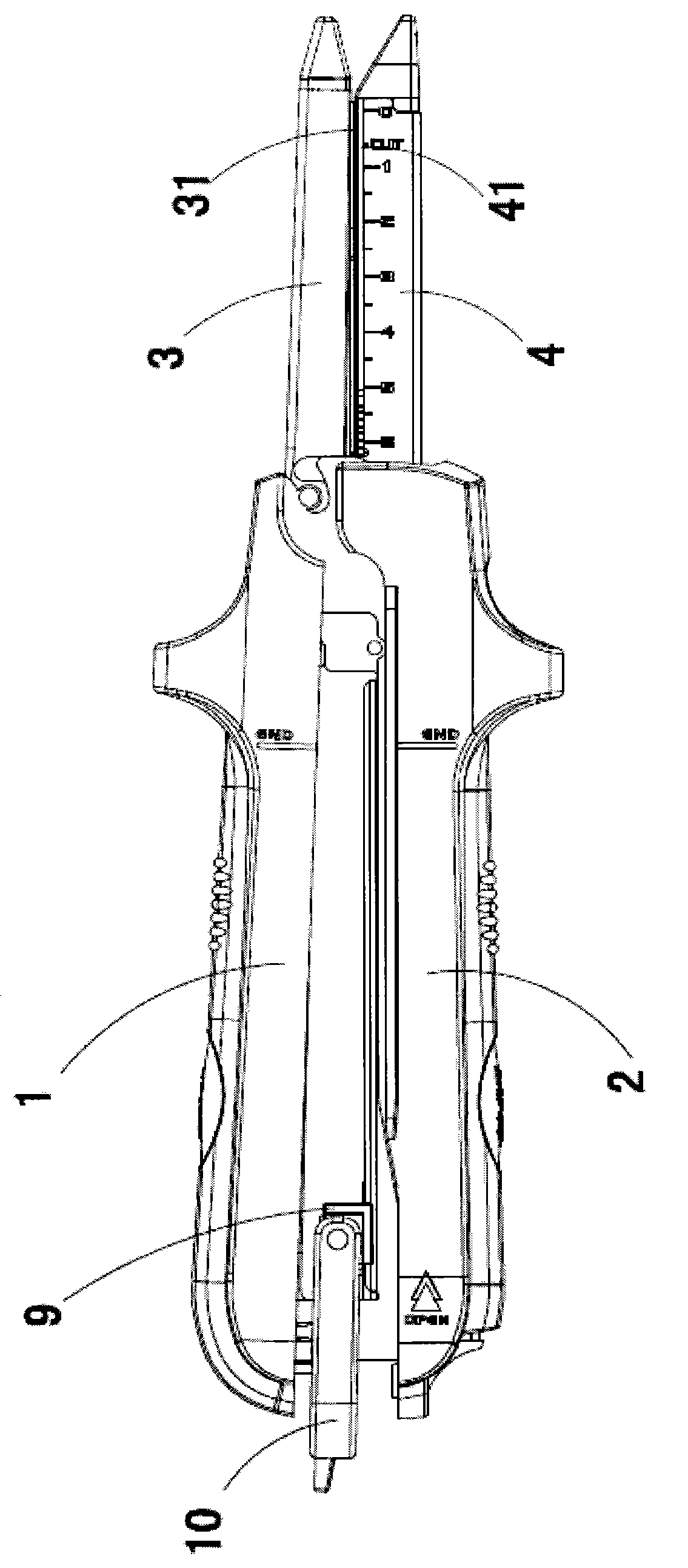
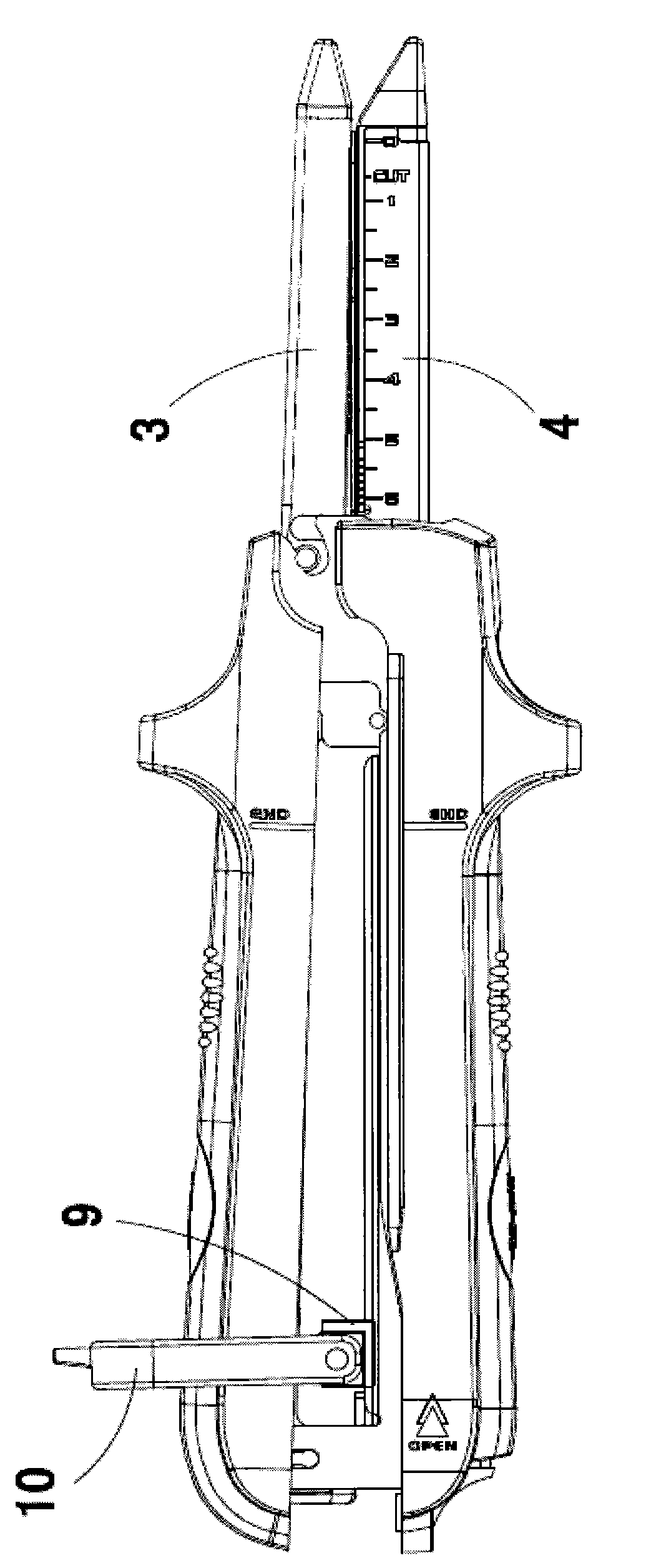
[0017] The invention discloses a medical linear staple cutting instrument, such as figure 1 As shown in the prior art, it includes: upper and lower jaws 1, 2 that can be closed or opened mutually, the far end of the upper jaw 1 is provided with an anvil 3, and the far end of the lower jaw 2 is provided with As for the staple cartridge 4, a closing handle for closing the upper and lower jaws is pivotally arranged on the lower jaw 2. When the upper and lower jaws 1 and 2 are closed, the anvil surface 31 of the anvil 3 and the staple cartridge surface 41 of the staple cartridge 4 are arranged oppositely and the tissue is clamped on the staple anvil surface 31 and the staple cartridge surface 41 In between, stapling and cutting can be performed at this time.

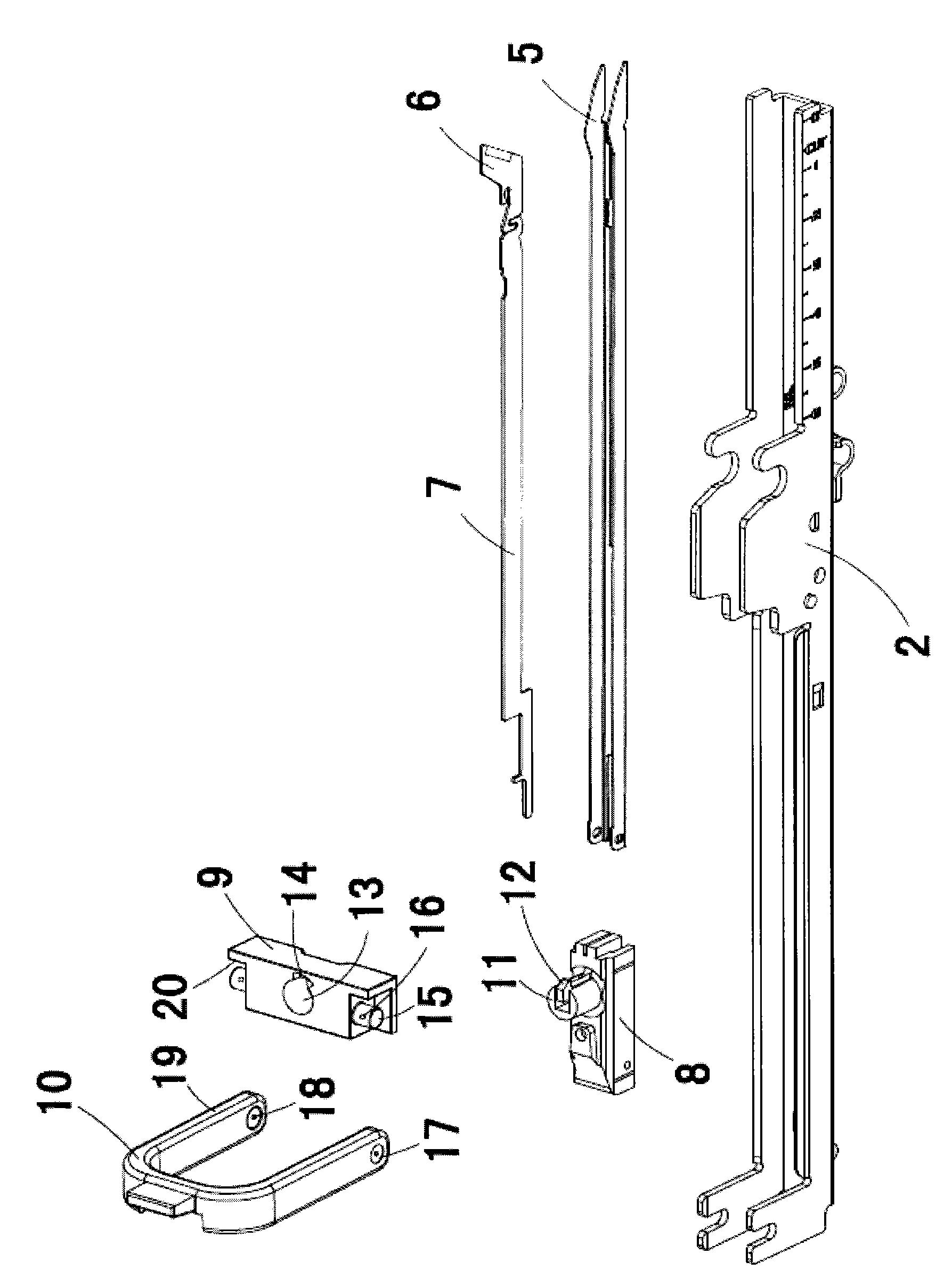
[0018] combine image 3 As shown, the lower jaw 2 is ∪-shaped, and a pusher rod 5 that can slide along the axis of the instrument and a pusher rod 7 with a cutter 6 at the far end are provided therein. The proximal ends o...


PUM


Abstract

The invention discloses a medical nailing incision instrument. The medical nailing incision instrument comprises an upper forceps holder, a lower forceps holder, and a nail anvil and a nail bin which are respectively arranged at the far ends of the upper and lower forceps holders oppositely, wherein a nail anvil surface and a nail bin surface are arranged in opposite to clamp tissues therebetween; a nail pushing rod capable of moving along the axis of the instrument and a cutter pushing rod with a cutter at the far end are arranged in the lower forceps holder, and the near ends of the nail pushing rod and the cutter pushing rod are arranged on a percussion block. A percussion cross rod is fixedly arranged on the percussion block, the percussion cross rod is pivoted with a U-shaped percussion wrench, and the U-shaped percussion wrench is arranged outside the upper and lower forceps holders in a bridged manner and can rotate between a first plane in parallel with the nail bin surface and a second plane perpendicular to the nail bin surface. The medical nailing incision instrument has the beneficial effects that the overall size of the instrument is reduced, and the packing and transport cost are reduced; the structure is simple, the assembly is convenient, and the medical nailing incision instrument is very practical.

Description

technical field [0001] The invention relates to a medical stapling device, in particular to a linear stapling and cutting instrument for surgery, which belongs to the technical field of medical instruments. Background technique [0002] Medical linear stapling and cutting instruments are widely used in wound suturing, internal tissue suturing and cutting. A typical linear stapling and cutting instrument, as disclosed in US Pat. No. 5,129,570, has two functions of suturing and cutting at the same time, that is, excess tissue is excised while suturing the wound. This type of instrument generally includes upper and lower jaws, an anvil and a staple bin that are relatively arranged at the far ends of the upper and lower jaws, and a closing handle for closing the upper and lower jaws; The pusher rod and the pusher rod with a cutter at the far end moving simultaneously along the axis of the instrument, one end of the pusher rod and the pusher rod are both arranged on a slider; th...

Claims


Application Information

Patent Timeline
IPC IPC(8): A61B17/072
CPCA61B17/07207A61B17/3209A61B2017/07214A61B2090/038
Inventor 陈望东舒拓裴永旺
Owner TOUCHSTONE INTERNATIONAL MEDICAL SCIENCE CO LTD
Why Eureka
Try Eureka