Field pipeline groove cutting machine
A cutting machine and pipeline technology, which is applied to the details of milling machine equipment, metal processing equipment, milling machine equipment, etc., can solve the problems such as the inability to effectively improve the cutting efficiency and quality of pipeline grooves, and achieve the improvement of cutting quality and pipeline welding quality. , the effect of increasing flexibility
- Summary
- Abstract
- Description
- Claims
- Application Information
AI Technical Summary
Problems solved by technology
Method used
Image
Examples
Embodiment 1
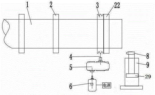
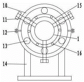
[0020] On-site pipeline bevel cutting machine of the present invention such as figure 1 Shown, comprise 2 chucks 2, driving chuck 22, belt pulley 3, speed changer 5, motor 6 and milling cutter equipment. Such as image 3 , Figure 4 Shown, active chuck and chuck are made of outer ring 10, inner ring 15 and support 14, and outer ring and inner ring are coaxially installed, and bearing 13 is housed between outer ring and inner ring, and bearing is ball bearing. The outer ring 10 is formed by buckling two semicircles, the two parts of the outer ring are fixed by bolts 12 , and the lower half of the outer ring is connected with the bracket 14 . The inner ring is provided with a positioning screw 11, and the positioning screw passes through the threaded hole 17 of the inner ring to clamp the pipeline to be processed. The inner ring of the active chuck is provided with screw holes 16, and the inner ring of the active chuck is fixedly connected with the belt pulley by bolts. The ...
Embodiment 2
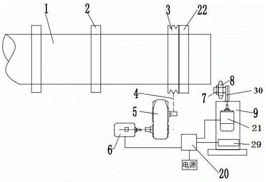
[0023] Another embodiment of the present invention is as figure 2 Shown, comprise 2 chucks 2, driving chuck 22, belt pulley 3, speed changer 5, motor 6, controller 20 and milling cutter equipment. Such as image 3 , Figure 4 Shown, active chuck is made of outer ring 10, inner ring 15 and support 14, and outer ring and inner ring are coaxially installed, and bearing 13 is housed between outer ring and inner ring, and bearing is roller bearing. The outer ring 10 is formed by buckling two semicircles, the two parts of the outer ring are fixed by bolts 12 , and the lower half of the outer ring is connected with the bracket 14 . The inner ring is provided with a positioning screw 11, and the positioning screw passes through the threaded hole 17 of the inner ring to clamp the pipeline to be processed. Such as Figure 5 , Figure 6 As shown, the chuck is composed of an inner ring 15, a roller 18 and a roller bracket 19. The inner ring is provided with a positioning screw 11, t...
Embodiment 3
[0025] The third embodiment of the present invention is as Figure 8 Shown, comprise 3 chucks 2, driving chuck 22, belt pulley 3, speed changer 5, motor 6 and milling cutter equipment. The left side of active chuck 22 is provided with 1 chuck, and the right side is provided with two chucks. Milling cutter equipment comprises groove milling cutter 8, milling cutter case 9, milling cutter moving mechanism 29, pipeline cutter 32, cutter motor and cutter moving mechanism 33. Milling cutter moving mechanism 29 and cutter moving mechanism are installed in the milling cutter case 9, the groove milling cutter is installed on the milling cutter moving mechanism, and the pipeline cutter is installed on the cutter moving mechanism by cutter bracket 34. The cutter motor is installed on the cutter bracket, and the pipeline cutter is coaxially connected with the cutter motor. The bevel milling cutter 8 and the pipeline cutter 32 on the milling cutter box can exchange positions with the cu...
PUM
 Abstract
Description
Claims
Application Information
 - R&D
- Intellectual Property
- Life Sciences
- Materials
- Tech Scout
- Unparalleled Data Quality
- Higher Quality Content
- 60% Fewer Hallucinations
Browse by: Latest US Patents, China's latest patents, Technical Efficacy Thesaurus, Application Domain, Technology Topic, Popular Technical Reports.
© 2025 PatSnap. All rights reserved.Legal|Privacy policy|Modern Slavery Act Transparency Statement|Sitemap|About US| Contact US: help@patsnap.com


