Automatic lock

A technology of automatic lock and lock shell, applied in the field of automatic lock, can solve the problems of complex structure of automatic lock and so on

Active Publication Date: 2014-05-21
WONLY SECURITY & PROTECTION TECH CO LTD
View PDF7 Cites 9 Cited by
  • Summary
  • Abstract
  • Description
  • Claims
  • Application Information

AI Technical Summary

Problems solved by technology

[0011] For this reason, the technical problem to be solved by the present invention is that the automatic lock in the prior art has a complex structure, and then provides an automatic lock with a simple structure.

Method used


Image

  • Automatic lock
  • Automatic lock
  • Automatic lock

Examples


Embodiment 1

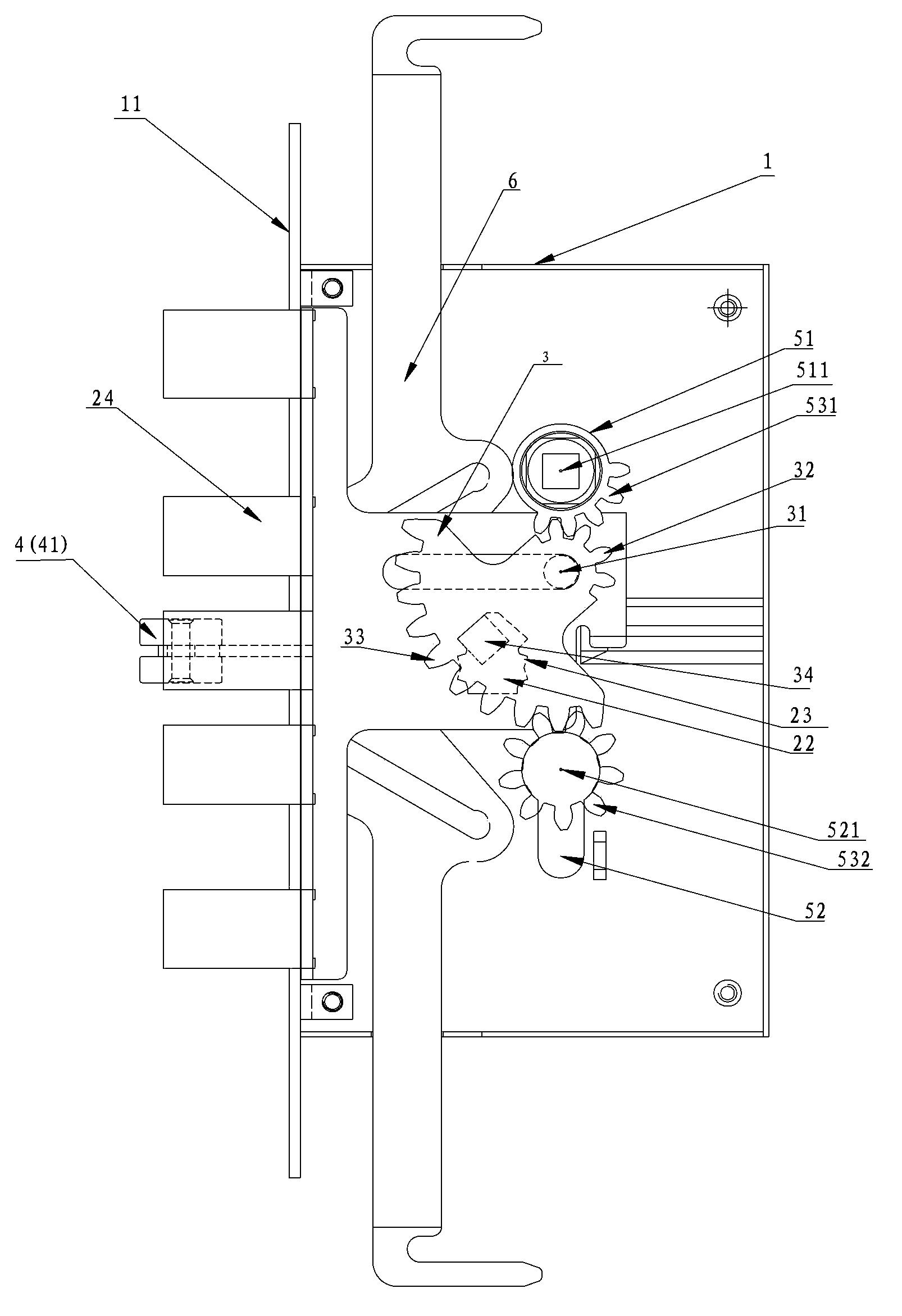
[0109] Figure 1-5 Shown is the implementation of the automatic lock described in this embodiment, including a lock case 1, a bolt member 2, a swing member 3 and a trigger assembly 4;

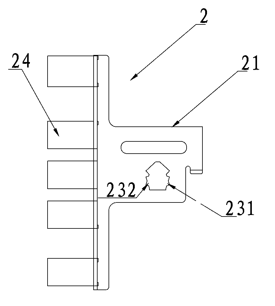
[0110] The lock tongue member 2 is arranged in the lock housing 1, and is limited to slide reciprocally between the lock-out terminal position and the lock-in terminal position along the lock-out direction A. In this embodiment, the lock tongue member 2 includes On the deadbolt plate 21 where the deadbolt 24 is installed, a traction groove 22 is formed on the deadbolt plate 21, and the edge of the traction groove 22 suitable for the action of the conflicting portion 34 is a guiding edge;

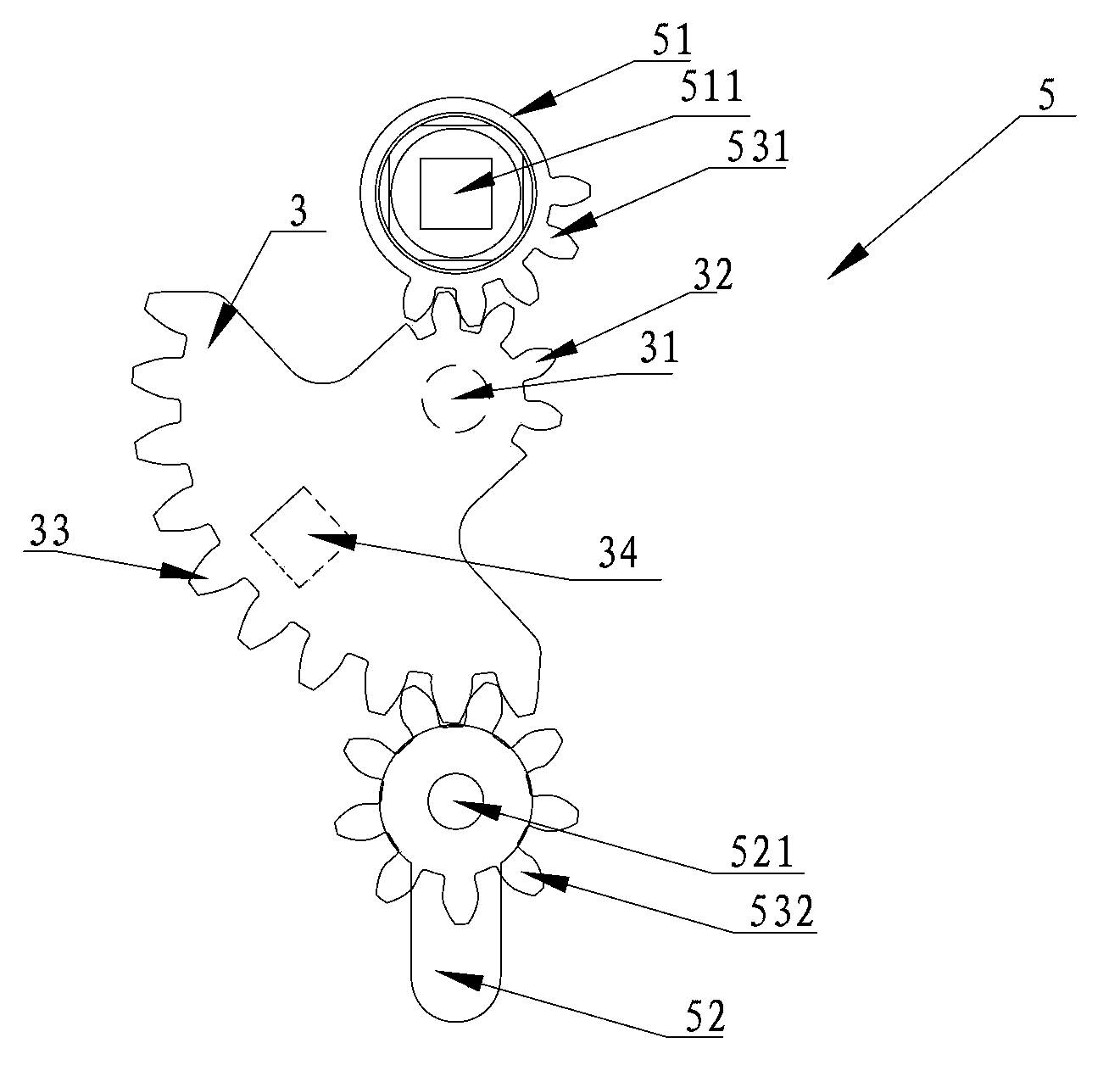
[0111] The swing member 3 is arranged in the lock case 1 and is rotatably mounted on the lock case 1; driven by the operating mechanism 5 to rotate around a fixed swing axis 31; between the operating mechanism 5 and the A transmission mechanism is provided between the swinging members 3, and the transmission...

Embodiment 2

[0123] Figure 6 Shown is the automatic lock described in this embodiment, including a lock case 1, a bolt member 2, a swing member 3 and a trigger assembly 4;

[0124] The lock tongue member 2 is arranged in the lock housing 1, and is limited to slide reciprocally between the lock-out terminal position and the lock-in terminal position along the lock-out direction A. In this embodiment, the lock tongue member 2 includes On the deadbolt plate 21 where the deadbolt 2 is installed, a traction groove 22 is formed on the deadbolt plate 21, and the edge of the traction groove 22 that is suitable for the action of the conflicting portion 34 is a guiding edge;

[0125] The swing member 3 is arranged in the lock case 1 and is rotatably mounted on the lock case 1; driven by the operating mechanism 5 to rotate around a fixed swing axis 31; between the operating mechanism 5 and the A transmission mechanism is provided between the swinging members 3, and the transmission mechanism includ...

Embodiment 3

[0150] Figure 17-18 Shown is the implementation of the automatic lock described in this embodiment, which includes a lock case 1, a bolt member 2, a swing member 3 and a trigger assembly 4;

[0151] The lock tongue member 2 is arranged in the lock housing 1, and is limited to slide reciprocally between the lock-out terminal position and the lock-in terminal position along the lock-out direction A. In this embodiment, the lock tongue member 2 includes On the deadbolt plate 21 where the deadbolt 24 is installed, a traction groove 22 is formed on the deadbolt plate 21, and the edge of the traction groove 22 suitable for the action of the conflicting portion 34 is a guiding edge;

[0152] The swing member 3 is arranged in the lock case 1 and is rotatably mounted on the lock case 1; driven by the operating mechanism 5, it rotates around a fixed swing shaft 31, preferably the swing shaft 31 is arranged on the The locking part 23 is located between the position of the lock-out term...


PUM


Abstract

The invention discloses an automatic lock, which comprises a lock case, a spring bolt component, a swing piece and a trigger component, wherein a locking part, which is arranged in a part in the lock case, is arranged on the spring bolt component; a swing shaft is arranged on a position, which is more biased to a lock-out direction than the locking part on a lock-in terminal position, and the swing piece is provided with a butting part; the spring bolt component is provided with a space, which is capable of further moving to the lock-in direction under the thrust of the trigger component, in the lock-in state; rotating partial pressure, which tends to rotate to the lock-out direction, is applied to the swing piece, and lock-out partial pressure, which is capable of pushing the spring bolt component out along the lock-out direction, is applied to the spring bolt component; self-locking pressure is formed between the locking part and the butting part on the lock-in position by the rotating partial pressure and the lock-out partial pressure. The automatic lock solves the technical problem of complicated structure of the automatic lock in the prior art, so that the automatic lock with the simple structure is further provided.

Description

technical field [0001] The invention relates to a lock, in particular to an automatic lock. Background technique [0002] Locks can be divided into entrance door locks (also known as anti-theft locks), room door locks, bathroom door locks, kitchen and passage locks according to their uses. Among them, the entrance door is the gate of every family and the watershed between the home and the outside. It must have a special function, that is, it can play the role of insurance and safety precautions. [0003] Chinese patent document CN102235119A discloses a kind of anti-theft automatic lock, which comprises a panel, a lock body, a lock head cam, a main bolt, a main bolt tooth plate, a push plate, a transmission hook, a cam piece, an oblique bolt with double-sided slopes, a transmission Rod, handle cam, the main bolt is fixed on the tooth plate of the main bolt, the tooth plate of the main bolt is movably arranged in the lock body, and the main bolt torsion spring is arranged bet...

Claims


Application Information

Patent Timeline
Patent Type & Authority Applications(China)
IPC IPC(8): E05B63/14E05B63/20E05B17/20E05B17/22E05B15/00E05B15/10
Inventor 王斌坚
Owner WONLY SECURITY & PROTECTION TECH CO LTD
Why Eureka
Try Eureka