Electric control hydraulic air distribution system for engine

An electronically controlled hydraulic and engine technology, which is applied in the direction of engine components, machines/engines, mechanical equipment, etc., can solve the difficult valve variable function of the camshaft valve system, the insensitive response of the camshaft driven valve, and the loss of engine pump air Large and other problems, easy to achieve the braking function in the cylinder, realize the braking function in the cylinder, and reduce the effect of pump air loss

Active Publication Date: 2014-05-21
GUANGXI YUCHAI MASCH CO LTD
View PDF5 Cites 12 Cited by
  • Summary
  • Abstract
  • Description
  • Claims
  • Application Information

AI Technical Summary

Problems solved by technology

[0003] The above scheme of using the camshaft to drive the valve to realize intake and exhaust control has the following disadvantages: it is difficult to realize the valve variable function (that is, to change the valve timing an

Method used


Image

  • Electric control hydraulic air distribution system for engine

Examples


Embodiment Construction

[0020] The specific embodiments of the present invention will be described in detail below in conjunction with the accompanying drawings, but it should be understood that the protection scope of the present invention is not limited by the specific embodiments.

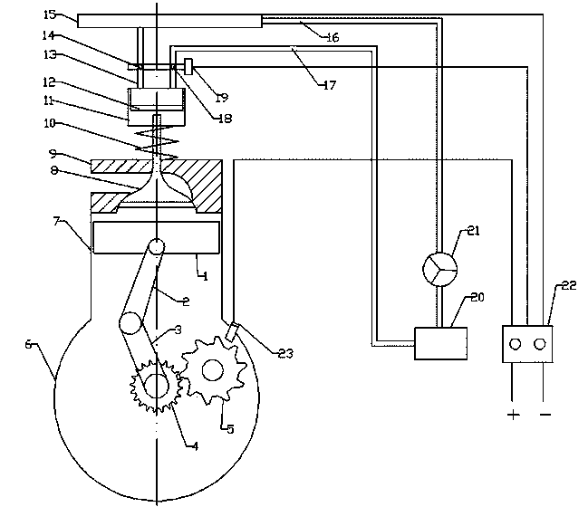
[0021] Such as figure 1 As shown, the engine electronically controlled hydraulic valve system of the present invention receives the signal from the signal plate sensor through the ECU, and controls the oil inlet and oil return of the valve mechanism, thereby controlling the movement of the piston of the valve mechanism in the hydraulic cylinder of the valve mechanism to drive the engine The valve opens or closes the intake and exhaust valves to obtain the timing and lift required by the valves.

[0022] further as figure 1 As shown, the gas distribution mechanism part specifically includes a hydraulic cylinder block 11 and a hydraulic piston 12. The hydraulic piston 12 can move up and down in the hydraulic cylinder bl...


PUM


Abstract

The invention discloses an electric control hydraulic air distribution system for an engine. The electric control hydraulic air distribution system comprises a cylinder body of a hydraulic air distribution mechanism, a piston execution mechanism, a hydraulic cylinder body oil inlet pipeline, a hydraulic cylinder body oil return pipeline, an ECU and an electromagnetic valve execution mechanism. The hydraulic air distribution mechanism comprises the hydraulic cylinder body and a piston. The piston is arranged inside the hydraulic cylinder body and can vertically move due to the combined action of the hydraulic pressure and a valve spring. One end of the hydraulic cylinder body oil inlet pipeline is communicated with the hydraulic cylinder body, and the other end of the hydraulic cylinder body oil inlet pipeline is communicated with an engine oil bottom shell. The end, close to the hydraulic cylinder body, of the hydraulic cylinder body oil inlet pipeline and the end, close to the hydraulic cylinder body, of the hydraulic cylinder body oil return pipeline are provided with an oil inlet hole and an oil return hole respectively. The ECU is in signal connection with the electromagnetic valve execution mechanism. The ECU controls the electromagnetic valve execution mechanism to open or close the oil inlet hole and the oil return hole by continuously receiving engine working status signals sent by a crankcase signal panel sensor, and therefore the hydraulic pressure inside the hydraulic cylinder body is controlled, and then opening, closing and the lift of an air valve are controlled. According to the electric control hydraulic air distribution system for the engine, the electric control fully variable function of the air valve of the engine can be achieved, and valve timing, the phase of the air valve and the lift of the air valve can be continuously adjusted.

Description

technical field [0001] The invention relates to the field of engines, in particular to an engine electronically controlled hydraulic gas distribution system. Background technique [0002] In the prior art solutions, the engine gas distribution system generally adopts a camshaft-driven valve solution to realize intake and exhaust control. Its working principle is: the camshaft is driven by the engine gear train to rotate, the intake and exhaust cams on the camshaft rotate synchronously with the camshaft and contact the valve according to the design state, and control the opening and closing time and valve lift of the intake and exhaust valves , to achieve engine intake and exhaust control. [0003] The above scheme of using the camshaft to drive the valve to realize intake and exhaust control has the following disadvantages: it is difficult to realize the valve variable function (that is, to change the valve timing and / or valve lift) with the designed camshaft distribution s...

Claims


Application Information

Patent Timeline
IPC IPC(8): F01L9/02F01L9/10F01L9/40
Inventor 陶泽民曾中马宁
Owner GUANGXI YUCHAI MASCH CO LTD
Why Eureka
Try Eureka