compressor

A technology for a compressor and a compression mechanism, applied in the field of compressors, can solve problems such as motor efficiency drop, lubricant temperature drop, compressor performance drop, etc., and achieve the effects of avoiding motor efficiency drop, optimizing cooling path, and improving performance

Active Publication Date: 2016-06-01
EMERSON CLIMATE TECH (SUZHOU) CO LTD
View PDF8 Cites 0 Cited by
  • Summary
  • Abstract
  • Description
  • Claims
  • Application Information

AI Technical Summary

Problems solved by technology

For example, for the high-pressure side design, under some operating conditions, the exhaust temperature may be higher than the temperature of the motor. At this time, the fluid discharged from the exhaust port can not cool the motor but heat the motor, resulting in a decrease in the efficiency of the motor and a decrease in the performance of the compressor.
For the low-pressure side design, under some operating conditions, the temperature of the sucked fluid may be much lower than the temperature of the motor. At this time, the cooling effect of the sucked fluid will cause the temperature of the lubricant to drop and the viscosity to rise, resulting in increased power consumption of the motor , the performance of the compressor is reduced

Method used


Image

  • compressor
  • compressor
  • compressor

Examples


Embodiment Construction

[0026] The following description of preferred embodiments is exemplary only and in no way restricts the invention and its application or usage. The same reference numerals are used to denote the same components in the respective drawings, and thus the configurations of the same components will not be described repeatedly.

[0027] The following will refer to Figure 1-4 The basic configuration and principle of the compressor 100 according to the first embodiment of the present invention will be described.

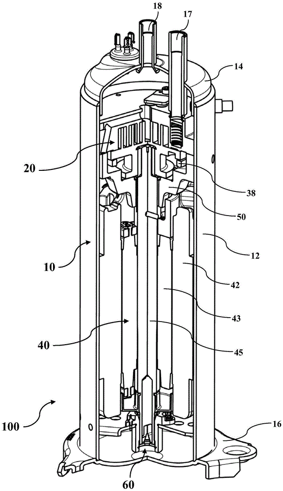
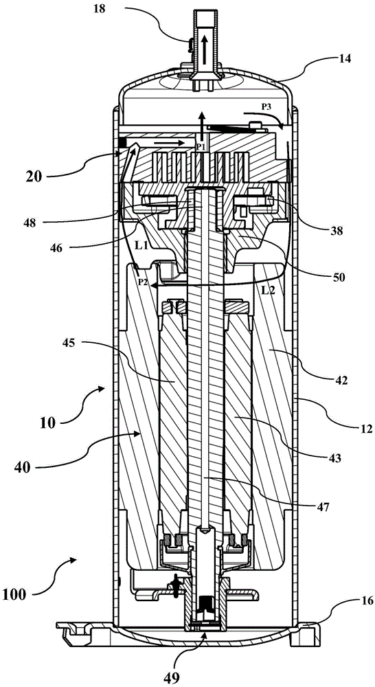
[0028] Such as figure 1 and 2 As shown, compressor 100 includes a generally closed housing 10 . The housing 10 defines an inner space of the compressor 100 . In the example in the figures, the housing 10 may be composed of a generally cylindrical body portion 12 , a top cover 14 , and a bottom cover 16 . These parts of the housing 10 can be connected to each other, for example, by bolts or any other suitable method.

[0029] A fluid inlet 17 and a fluid outlet 18 may ...


PUM


Abstract

The invention relates to a compressor (100, 200, 300 or 400). The compressor comprises a case (10) and a compression mechanism (20), wherein the case defines the inner space of the compressor, and a fluid inlet (17) and a fluid outlet (18) are arranged on the case; the compression mechanism is arranged in the case (10) to compress a fluid and comprises an air suction port (27) and an exhaust port (28); and the inner space comprises a first flow velocity area (P1) and a second flow velocity area (P2), the flow velocity of the fluid in the first flow velocity area is higher than that of the fluid in the second flow velocity area, and a first fluid channel (L1) allowing the fluid to flow to the first flow velocity area from the second flow velocity area is constructed in the inner space. According to the compressor, specific areas of the inner space of the compressor can be effectively and appropriately cooled.

Description

technical field [0001] The present invention relates to a compressor. Background technique [0002] The statements in this section merely provide background information related to the present disclosure and may not constitute prior art. [0003] Compressors are usually used to compress refrigerants for cooling or heating. The compression mechanism of the compressor is driven by a drive mechanism such as a motor. Both the compression mechanism and the drive mechanism are usually housed in a closed housing. During normal operation of the compressor, the internal space of the compressor, especially the drive mechanism, needs proper cooling. [0004] In the compressor of the prior art, a fluid inlet and a fluid outlet are generally formed at both ends of the housing or at the part of the housing opposite to the compression mechanism, so that all or part of the fluid sucked through the fluid inlet or the compression mechanism can be All or part of the fluid discharged from th...

Claims


Application Information

Patent Timeline
Patent Type & Authority Patents(China)
IPC IPC(8): F04B39/06
Inventor 束宏飞孙庆丰慎世珍
Owner EMERSON CLIMATE TECH (SUZHOU) CO LTD
Why Eureka
Try Eureka