Throttle valve for oil gas

A choke valve, oil and gas technology, applied in the direction of lift valve, valve device, wellbore/well valve device, etc., can solve the problems of poor sealing performance, unfavorable on-site maintenance, complex structure of choke valve, etc., to improve the sealing effect , enhance the mechanical properties, enhance the effect of sealing

Inactive Publication Date: 2014-05-21
DEYANG ZHENGGUANG PETROLEUM MASCH MFG CO LTD
View PDF9 Cites 4 Cited by
  • Summary
  • Abstract
  • Description
  • Claims
  • Application Information

AI Technical Summary

Problems solved by technology

From the analysis of the working principle of the throttle valve and the use environment, there are currently two ways to increase the service life of the throttle valve. One is to change the structure of the throttle valve, adjust the flow direction of the medium, and control the erosion direction of the medium on the pressure control parts. Reduce the erosion of the medium on the parts to achieve the purpose of increasing the service life. Now many manufacturers at home and abroad are using this method to improve the life of the throttle valve. From the needle throttle valve before 1925 to the current cage type Throttle valves, during this period, diaphragm type throttle valves and plunger type throttle valves also appeared. Recently, some manufacturers have developed labyrinth throttle valves. Through these improvements, the life of throttle valves has also been improved. A certain improvement, but this improvement makes the structure of the throttle valve complicated, which is not conducive to on-site maintenance
The second is to improve the material of the pressure control parts and increase the hardness of the material to directly enhance the erosion resistance of the parts. Initially, the surface hardness of the parts is improved by surfacing cobalt-based or nickel-based alloys, which can increase the surface hardness of the parts to 45~ 60HRC, but the actual effect is not ideal, and then the whole hard alloy is used to make the pressure control part, its life has been significantly improved, but due to the cost of the throttle valve, the actual sales effect is not too ideal
In the above technical solution, the structure between the valve core and the valve seat is relatively complicated, especially the sealing performance is poor.

Method used


Image

  • Throttle valve for oil gas
  • Throttle valve for oil gas

Examples


Embodiment 1

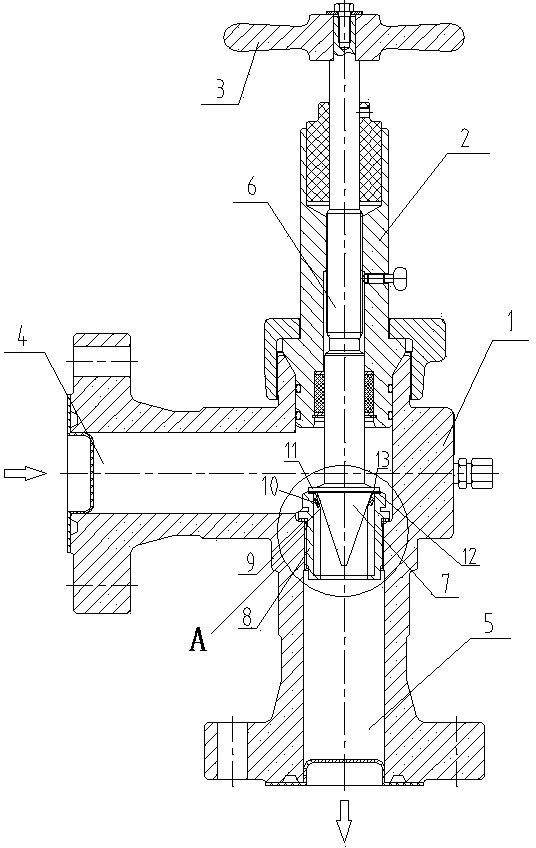
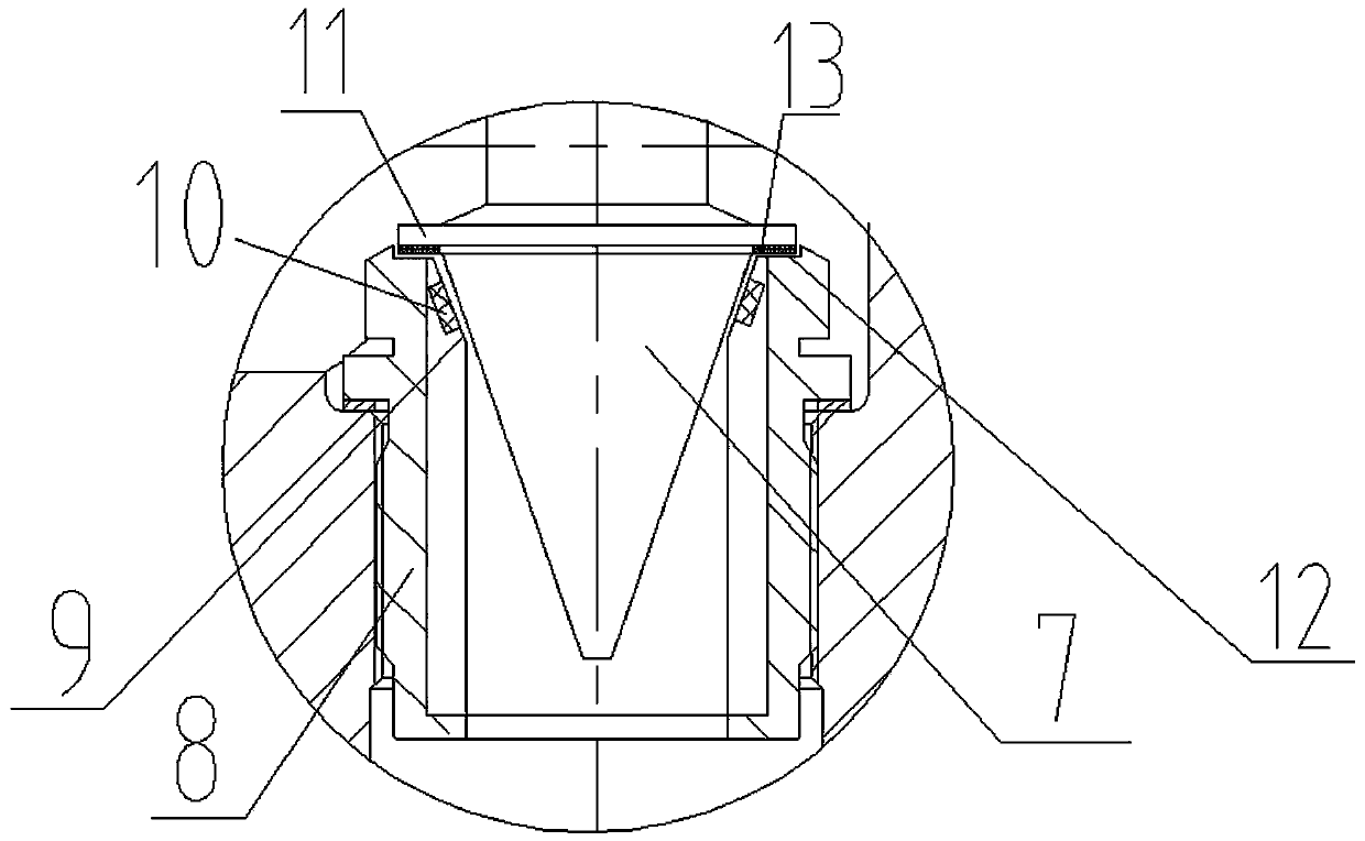
[0020] Such as figure 1 , figure 2 As shown, a throttle valve for oil and gas includes a valve body 1, a valve cover 2, a valve stem 6, a valve core 7, and a valve seat 8. The valve body 1 is provided with a medium inflow channel 4 and a medium outflow channel 5 , the medium inflow channel 4 and the medium outflow channel 5 are vertically arranged, the valve seat 8 is embedded in the medium outflow channel 5, and one end of the valve stem 6 passes through the valve cover 2 and extends to the outside of the valve cover 2 , is connected with the driving handle 3, the other end of the valve stem 6 is connected with the valve core, and the rotation of the driving handle 3 drives the valve stem 6 to rotate, and the valve core 7 and the valve seat 8 are driven by the valve stem 6 to control the flow of the medium. The spool 7 is conical, and the conical spool 7 is inverted to match the valve seat 8. The upper part of the inverted spool 7 protrudes outwards to form a flange 11, whi...


PUM


Abstract

The invention discloses a throttle valve for oil gas. The throttle valve comprises a valve body, a valve cover, a valve rod, a valve core and a valve seat. The valve seat is provided with a medium inflow channel and a medium outflow channel which are perpendicular to each other. The valve seat is embedded into the medium outflow channel. One end of the valve rod penetrates through the valve cover, extends outside the valve cover and is connected with a drive handle, the other end of the valve rod is connected with the valve core, and the valve core and the valve seat are driven by the valve rod to be used in cooperation with each other to control medium flow. The throttle valve is characterized in that the valve core is in the shape of a cone and is inverted to be matched with the valve seat, the upper portion of the inverted valve core protrudes outwards to form a flange, a sealing ring is arranged on the lower surface of the flange, and the upper portion of the valve seat caving downwards to form a step. When the valve rod is screwed tightly, the flange of the valve core and the step are sealed in a matched mode. The service life of the throttle valve is prolonged, and sealing performance of the throttle valve is greatly improved.

Description

technical field [0001] The invention belongs to the technical field of valves, in particular to a throttle valve for oil and gas. Background technique [0002] The throttle valve is a valve that controls the fluid flow by changing the throttle section or throttle length. If the throttle valve and the check valve are connected in parallel, it can be combined into a one-way throttle valve. The throttle valve and the one-way throttle valve are simple In the quantitative pump hydraulic system, the throttle valve and the overflow valve cooperate to form three kinds of throttling speed regulation systems, namely, the throttle speed regulation system of the inlet oil circuit, the throttle speed regulation system of the oil return circuit and the Bypass throttling speed control system. [0003] Wellhead choke valves are mainly used for production throttling, to control flow, optimize production, and reduce wellhead pressure to the applicable pressure range. It can also be used for...

Claims


Application Information

Patent Timeline
Patent Type & Authority Applications(China)
IPC IPC(8): F16K1/00F16K1/38F16K1/42
CPCF16K1/00E21B34/02F16K1/385F16K1/42
Inventor 周宁康林建国段太建
Owner DEYANG ZHENGGUANG PETROLEUM MASCH MFG CO LTD
Why Eureka
Try Eureka