
Lens for LED lamp

A technology of LED lamps and lenses, applied in the parts of lighting devices, lighting devices, light sources, etc., can solve the problems of reduced light output efficiency, reduced light energy, affecting product performance, etc., to reduce glare, large light output surface, and light output efficiency. high effect

Active Publication Date: 2014-05-21
ZHEJIANG SHENGHUI LIGHTING
View PDF5 Cites 3 Cited by
  • Summary
  • Abstract
  • Description
  • Claims
  • Application Information

AI Technical Summary

Problems solved by technology

Therefore, in order to increase the area of ​​the light-emitting surface, the height of the lens can only be increased proportionally. However, as the height of the lens increases, the light energy will also decrease with the increase of the propagation distance, which will reduce the light-emitting efficiency; The space becomes smaller, which affects the performance of the product

Method used


Image

  • Lens for LED lamp
  • Lens for LED lamp
  • Lens for LED lamp

Examples


Embodiment Construction

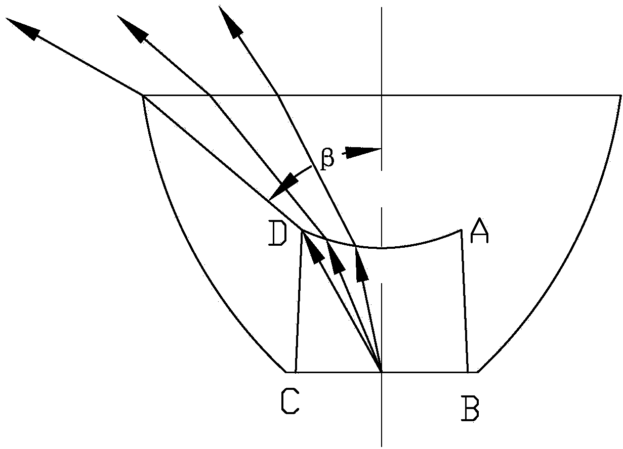
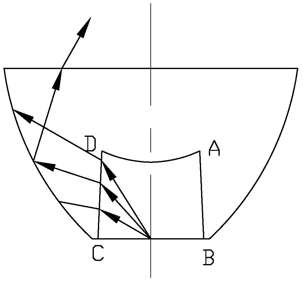
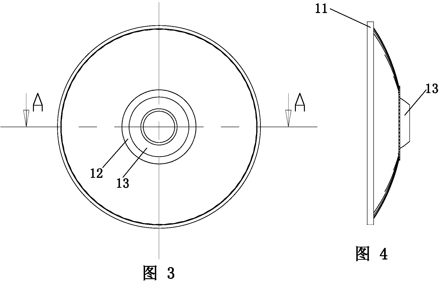
[0026] like Figure 3 to Figure 7 As shown, a lens for LED lights, the lens is basically in the shape of a truncated cone in structure, including a bottom surface with a small diameter, a top surface and a side surface with a large diameter, the top surface is a light-emitting surface, and the top surface is along the periphery of the top surface. An annular boss 11 extends outward, and a groove 12 is provided on the bottom surface of the lens. The cross section of the groove 12 is circular, and the inner diameter of the groove 12 gradually decreases from the outside to the inside. There is a protrusion 13, which protrudes from the bottom surface of the lens. The protrusion 13 is in the shape of a truncated cone as a whole. Put cavity 14, light source accommodating cavity 14 has the incident side surface that makes light enter lens, incident top surface, the shape of each part of this lens, size adopts following method to design:

[0027] Define the lens height as H1, the len...


PUM


Abstract

The invention discloses a lens for an LED lamp. A groove is formed in the bottom face of the lens, the cross section of the groove is circular, the inner diameters of the groove are gradually reduced from outside to inside, a protrusion is further arranged in the groove and protrudes out of the bottom face of the lens, the whole protrusion is in a circular truncated cone shape, the diameters of the cross sections of the protrusion are gradually reduced from inside to outside, a light source containing cavity is formed in the protrusion, and an opening is formed in the bottom. According to the lens, on the basis of the lens structure, the shape and the size of the lens are ingeniously designed, simulation is achieved through a computer, finally a designed graph is led into computer simulation software to conduct design simulation, a light path is detected to conduct local optimization, and the lens meets the design requirement finally. The lens for the LED lamp has the advantages that the light-emitting area is larger, and the surface brightness of the lens is reduced; the height of the lens is reduced, and space is saved for radiating and a power source; the thickness of the lens is reduced, the cost of the lens can be saved, meanwhile, the shaping time of the lens is shortened, and the cost of the lens is substantially reduced.

Description

technical field [0001] The invention relates to the field of LED lighting, in particular to a lens for an LED lamp. Background technique [0002] The LED fully transparent reflective lens can distribute the luminous flux of the LED lamp beads within the 2π solid angle, and the luminous flux utilization rate is high, which can reach more than 85%, and the installation is easy. The lens is easy to process and has a small volume, which requires little space and is suitable for installation in various lamps. At present, lamps equipped with LED lenses have been widely used, such as architectural lighting, general lighting, sign lighting, landscape lighting, traffic lights, etc. have been well used. With the continuous improvement of LED technology, the prospect of LED lens will be better. [0003] Existing lenses are designed according to Snell's law. Generally speaking, the lens adopts a bowl-shaped structure with rotational symmetry and a hollow bottom. [0004] like figur...

Claims


Application Information

Patent Timeline
IPC IPC(8): F21V5/04F21Y101/02
Inventor 陈方沈锦祥
Owner ZHEJIANG SHENGHUI LIGHTING
Features
  • Generate Ideas
  • Intellectual Property
  • Life Sciences
  • Materials
  • Tech Scout
  • Unparalleled Data Quality
  • Higher Quality Content
  • 60% Fewer Hallucinations
Learn More