Cavity filter and screw device

A cavity filter and cavity technology, applied in the field of communication, can solve the problems of large space occupied by nut 2 and shrapnel 3, many matching parts, and time-consuming installation, so as to save external space, not easy to loosen, and improve production efficiency Effect

Active Publication Date: 2014-05-21
ANHUI TATFOOK TECH CO LTD
View PDF10 Cites 4 Cited by
  • Summary
  • Abstract
  • Description
  • Claims
  • Application Information

AI Technical Summary

Problems solved by technology

However, this kind of anti-loosening mechanism has many matching parts, and the installation is time-consuming; and the nut 2 and the shrapnel 3 take up a lot of space
[0006] In summary, the existing screw device obviously has inconvenience and defects in actual use, so it is necessary to improve it

Method used


Image

  • Cavity filter and screw device
  • Cavity filter and screw device
  • Cavity filter and screw device

Examples


Embodiment 1

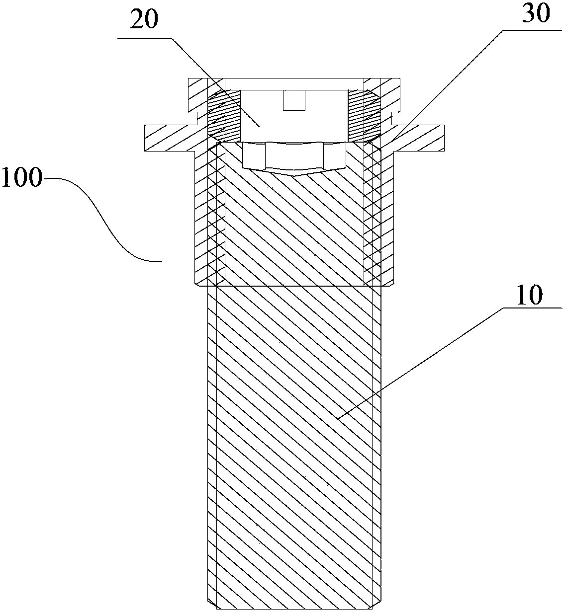
[0020] like figure 2 As shown, this embodiment provides a screw device 100, including a first screw 10 and a locking member 20 for locking the first screw 10, the first screw 10 and the locking member 20 are screwed together In the threaded hole 30, one end of the locking member 20 is docked with one end of the first screw rod 10 to generate a pre-tightening force to lock the first screw rod 10, and the other end surface of the locking member 20 does not protrude from the first screw rod 10. The above threaded hole 30.

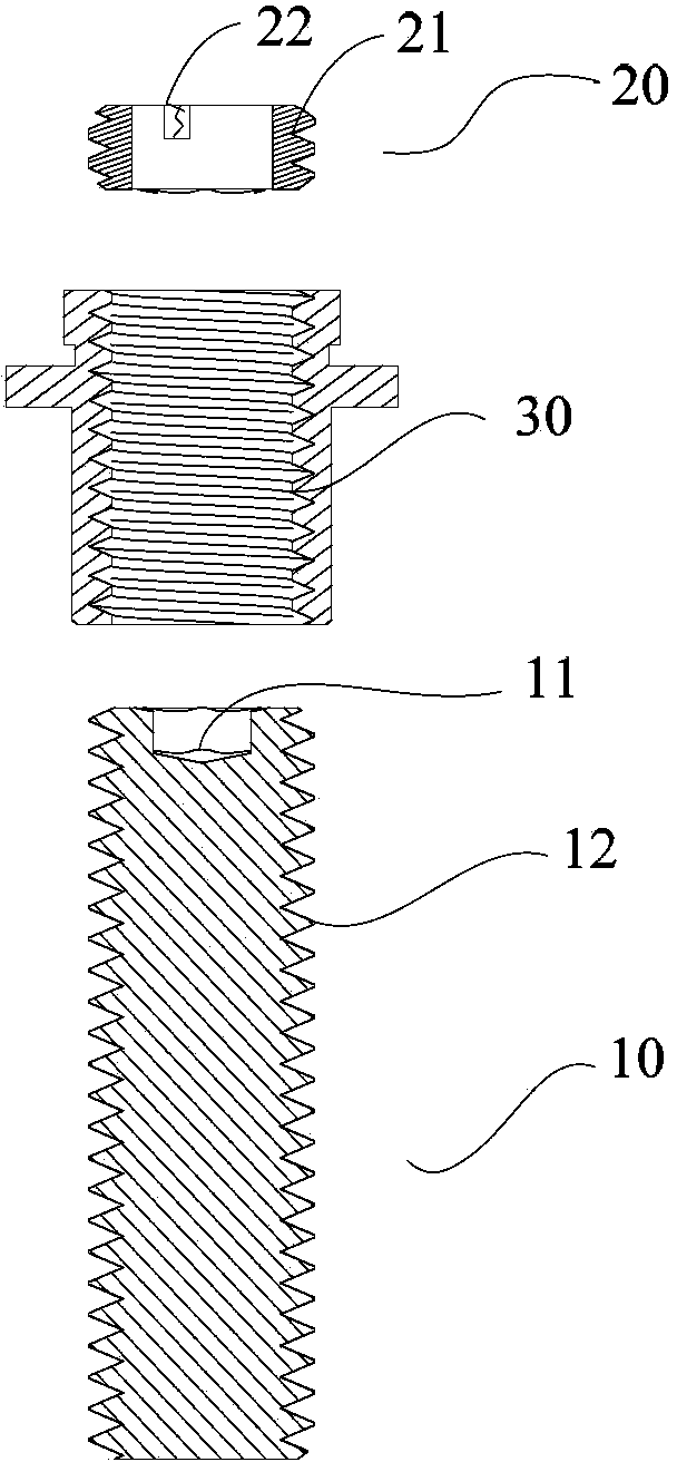
[0021] Specifically, refer to image 3 and Figure 4 , The locking member 20 is preferably an annular body with an external thread 21, and the annular body is used to allow an external workpiece to pass through during installation to position the first screw rod. The end face of one end of the locking member is provided with a notch 22 for screwing the locking member into the threaded hole. The notch can be preferably two symmetrical notches, and certainly...

Embodiment 2

[0028] This embodiment provides a cavity filter 200, refer to Figure 5 , including a closed cavity 210 composed of at least one face, and a tuning screw device 100 assembled on at least one face, the tuning screw device can be referred to together figure 2 , image 3 and Figure 4 , the tuning screw device 100 includes a tuning screw 10 that is at least partially threaded with the cavity 210 and a locking member 20 for locking the tuning screw, the tuning screw 10 and the locking member 20 are both screwed In the threaded hole 30 on the cavity, one end of the locking member 20 is docked with one end of the tuning screw 10 to generate a pre-tightening force to lock the tuning screw 10, and the other end of the locking member 20 is not convex. out of the threaded hole 30 .

[0029] The tuning screw device 100 on the installation cavity 210 is used to adjust the radio frequency parameters in the filter cavity, and the radio frequency parameters are changed by adjusting the d...


PUM


Abstract

The invention discloses a cavity filter comprising an enclosed cavity formed at least one surface, and a tuning screw device assembled on at least one surface. The tuning screw device comprises a tuning screw rod at least partially in threaded connection with the cavity and a locking member for locking the tuning screw rod. The tuning screw rod and the locking member are screwed in a threaded hole on the cavity. One end of the locking member is in abutting joint with one end of the turning screw rod to generate a pre-tightening force to lock the tuning screw rod. The other end of the locking member does not protrude from the threaded hole. The screw rod of the tuning screw device of the cavity filter provided by the invention has a good locking effect and is not liable to loosen. And the screw device can be arranged under a locking workpiece surface, so that the external space of the locking workpiece is reduced. The tuning screw rod and the locking member are easy to process and can be repeatedly used.

Description

technical field [0001] The invention relates to the communication field, in particular to a cavity filter and a screw device. Background technique [0002] As a frequency selection device, filters are widely used in the field of communication, especially in the field of radio frequency communication. In the base station where the communication system completes signal transmission and reception, the filter is used to select the communication signal and filter out the clutter or interference signal outside the frequency of the communication signal. [0003] At present, in mobile communication base station systems, cavity filters are commonly used to select frequencies for signals transmitted and received by antennas. The cavity filter includes a cavity body and a cover plate, and a plurality of cavities are arranged on the cavity body. A resonant tube is formed on the bottom of each cavity in the cavity. The interior of the resonant tube is hollow, forming a resonant cavity...

Claims


Application Information

Patent Timeline
Patent Type & Authority Applications(China)
IPC IPC(8): H01P1/207
Inventor 张明俊
Owner ANHUI TATFOOK TECH CO LTD
Why Eureka
Try Eureka