
Vehicle driving force control device

一种控制装置、驱动力的技术,应用在控制装置、发动机控制、电气控制等方向,能够解决不充分、受损、无法产生行驶特性或加速特性等问题,达到增大驱动转矩、加速性良好的效果

Inactive Publication Date: 2014-05-21
TOYOTA JIDOSHA KK
View PDF7 Cites 8 Cited by
  • Summary
  • Abstract
  • Description
  • Claims
  • Application Information

AI Technical Summary

Problems solved by technology

When the required power is increased from this state to perform re-acceleration, the engine speed increases to the specified speed at the operating point on the power line, so the range of change (change amount) of the engine speed increases, and the engine speed increases during re-acceleration. When , the torque consumed to increase the engine speed increases, and the re-acceleration performance may be impaired
[0005] In addition, the device described in the aforementioned Japanese Patent Application Laid-Open No. 2005-76673 is configured to maintain the engine speed at a high level by prohibiting upshifting when entering a corner or during corner running in order to improve the acceleration performance when reaccelerating when leaving a corner. Based on the premise of technology, the necessary minimum engine speed at this time is maintained. However, the necessary minimum engine speed is mainly obtained based on running resistance. Therefore, even if sufficient driving force can be obtained to overcome running resistance, it may not be able to produce sufficient response. Possibility of driving characteristics or acceleration characteristics as intended by the driver
[0006] In addition, the above-mentioned International Publication No. 2011 / 021634 discloses a technique of increasing an indicator when the magnitude of the combined acceleration changes, a technique of maintaining the indicator, or a technique of suppressing a decrease, but in the state of maintaining a high value of the indicator When the deceleration operation and the acceleration operation are performed continuously, the technology disclosed in the above-mentioned International Publication No. 2011 / 021634 is insufficient in order to realize the driving intention expressed as a high-value indicator as the actual behavior of the vehicle. There is still room for improvement

Method used

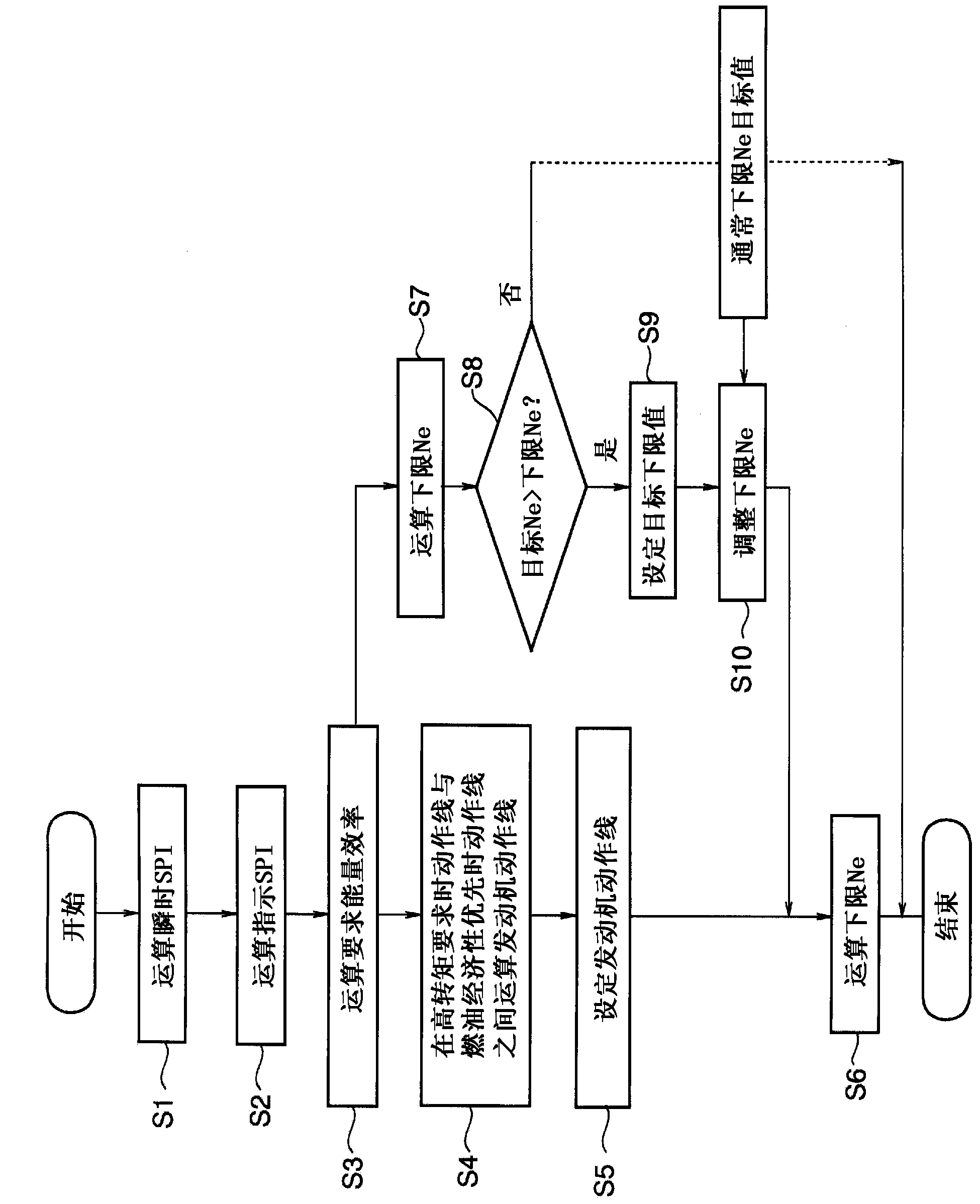
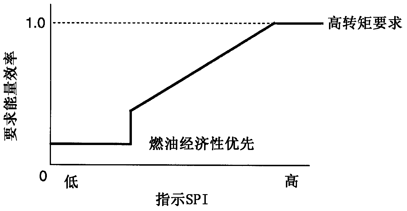
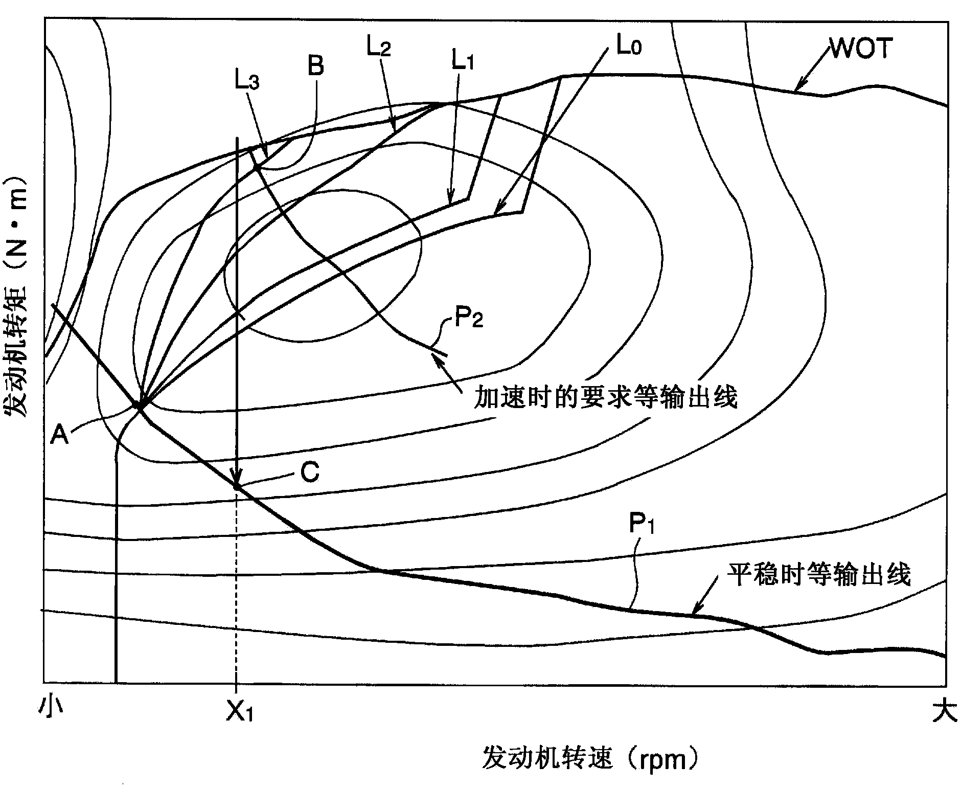

Image

  • Vehicle driving force control device
  • Vehicle driving force control device
  • Vehicle driving force control device

Examples


Embodiment Construction

[0022] The vehicle targeted by the present invention is a vehicle that uses an internal combustion engine as a driving force source, or a vehicle that includes an engine as a driving force source, and is a vehicle that can control the rotational speed of the engine to an appropriate target rotational speed. This specific example is a hybrid vehicle and a vehicle equipped with a continuously variable transmission.

[0023] Figure 5 An example of a power train of a hybrid vehicle is schematically shown. The engine 1 is connected to a power split mechanism 2 that splits the power output by the engine 1 . The power split mechanism 2 is mainly a mechanism that performs differential action through three rotating elements. Figure 5 In the shown example, it is constituted by a single-pinion type planetary gear mechanism, and includes a sun gear 3, a ring gear 4, and a carrier 5 as rotating elements, wherein the ring gear 4 is arranged on a concentric circle concentric with the sun...


PUM


Abstract

A vehicle driving force control device that is capable of selecting a first mode and a second mode with regard to a target rotational speed of an engine serving as a driving force source, said first mode setting the rotational speed such that a target output can be achieved with an optimal fuel consumption, and said second mode setting the rotational speed of the engine lower than the rotational speed for achieving the target output with the optimal fuel consumption, and selectively setting either the first mode or the second mode on the basis of an index which represents a driver's intent of driving, which is configured such that the vehicle driving force control device sets a lower limit on the rotational speed according to the index while the second mode is selected, and restricts the lower limit value of the target rotational speed to the lower limit rotational speed when the target rotational speed of the engine has exceeded the lower limit on the rotational speed while the second mode is selected.

Description

technical field [0001] The present invention relates to a device for controlling driving force of a vehicle, and more particularly to a device for controlling the output of an engine (internal combustion engine) provided as a driving force source so as to conform to a driver's driving intention (preference or orientation). Background technique [0002] The driving force source of the vehicle, that is, the rotational speed and output torque of the engine will greatly affect the driving performance, acceleration performance or fuel economy performance of the vehicle. Recently, attempts have been made to appropriately control the rotational speed and output torque of the engine separately. This example is a hybrid vehicle or a vehicle equipped with a continuously variable transmission that can control the rotational speed of the engine by an electric motor. Effectively utilizing such a control function to Improve driving performance and fuel economy performance. [0003] For e...

Claims


Application Information

Patent Timeline
Patent Type & Authority Applications(China)
IPC IPC(8): F02D29/02F02D45/00
CPCF02D29/02B60K31/00B60W10/06B60W30/1882B60W2710/0644F02D11/105F02D31/001Y10S903/903
Inventor 竹内启祐鹤冈一夫棚桥敏雄安形义满金子博贵鹤村幸司
Owner TOYOTA JIDOSHA KK
Learn More