Non-returning type intermittent iron remover

A kind of iron remover, intermittent type technology, applied in the field of non-returning type intermittent iron remover, can solve the problems of long time consumption of returning ore slurry, great influence, no product output, etc., so as to increase the time of ore extraction and reduce Chemical cost, effect of reducing mechanical inclusion

Active Publication Date: 2016-04-13
佛山市易升达磁电技术有限公司
View PDF10 Cites 0 Cited by
  • Summary
  • Abstract
  • Description
  • Claims
  • Application Information

AI Technical Summary

Problems solved by technology

[0003] The iron remover with the above structure adopts the process of returning to the ore pulp, and generally returns the ore naturally or under pressure. These two methods will inevitably bring the ferromagnetic minerals adsorbed on the magnetic medium in the working chamber back to the original ore slurry. Among them, especially weakly magnetic minerals, resulting in greater pollution; thirdly, in the process of returning to the pulp, most of the pulp in the working chamber has undergone the iron removal process, and when returning to the pulp mixing tank, the excitation is still in the work, resulting in the consumption of electric energy, but no product output, resulting in the processed products to be iron-removed again, repeated work, which increases the workload of the iron remover, especially the larger the processing equipment, the greater the impact, which limits the The large size of the equipment and the long time it takes to return the slurry reduce the working efficiency of the iron remover

Method used


Image

  • Non-returning type intermittent iron remover
  • Non-returning type intermittent iron remover
  • Non-returning type intermittent iron remover

Examples


Embodiment Construction

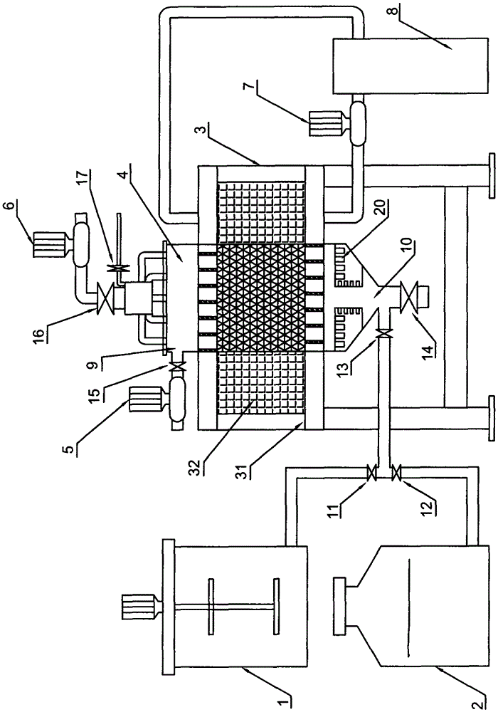
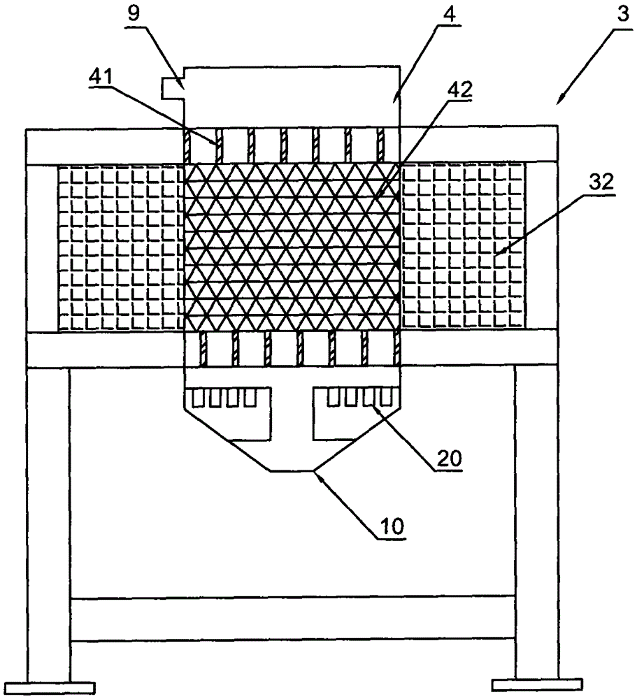
[0016] refer to figure 1 , figure 2 , non-returning type intermittent iron remover, including the iron remover body 3, the iron remover body 3 includes a frame 31 and a working cavity 4 arranged on the frame 31, and a winding is arranged outside the working cavity 4 The coil 32, the working chamber 4 is provided with a magnetically conductive pole plate 41 and a magnetic gathering medium 42, and an upper port 9 and a lower port 10 are respectively arranged on the upper and lower parts of the working chamber 4, and there are a slurry outlet pipe and an upper port 9 connection, a slurry valve 15 and a slurry pump 5 are sequentially provided at the port of the slurry outlet, and the lower port 10 is connected with a pipeline and an iron discharge pipe, and a pipeline valve 13 and an iron discharge valve are respectively provided on the pipeline and the iron discharge pipe 14. The other end of the pipeline is connected with a slurry inlet pipe and a water inlet pipe respectively...


PUM


Abstract

The invention discloses an ore returning-free intermittent iron-removing machine. The ore returning-free intermittent iron-removing machine comprises a iron-removing machine main body, wherein a slurry outlet pipe is connected with an upper opening of a working cavity of the main body; a slurry outlet valve and a slurry pump are sequentially arranged on the end opening of the slurry outlet pipe; a pipe and an iron discharging pipe are communicated with the lower opening of the working cavity; a pipe valve and an iron discharging valve are respectively arranged on the pipe and the iron discharging pipe; a slurry inlet pipe and a water inlet pipe are respectively communicated with the other end of the pipe; a slurry inlet valve and a water inlet valve are respectively arranged on the slurry inlet pipe and the water inlet pipe; an ore pulp mixing tank and a constant pressure water tank are respectively communicated with the slurry inlet valve and the water inlet valve; the top of the working cavity is connected with a high-pressure water pump through a rinsing pipe; a rinsing water valve is arranged on the rinsing pipe; an ultrasonic oscillator is further arranged in the working cavity. The ore returning-free intermittent iron-removing machine is reasonable in structure, low in energy consumption, high in efficacy, and better in ore pulp iron-removing effect, and can be widely applied to carrying out wet separation and removing iron-containing impurities from ceramic raw materials, non-metallic mine and the like.

Description

technical field [0001] The invention relates to a fluid iron remover for wet separation of ceramic raw materials and non-metallic ores to remove iron-containing impurities, in particular to a non-return type intermittent iron remover. Background technique [0002] At present, the traditional fluid iron remover on the market that separates ceramic raw materials, ore pulp, etc., and removes iron-containing impurities includes the body of the iron remover. The body of the iron remover includes a frame and a working chamber arranged on the frame. There is a winding coil outside the working chamber, and a magnetically conductive pole plate and a magnetic gathering medium are installed in the working chamber. The slurry mixing tank is connected to the working chamber through the pulp inlet pipe, and the pulp outlet pipe is connected to the upper port of the working chamber. There is a cleaning pipe, and the lower port of the working cavity is connected with a slurry inlet pipe, a ...

Claims


Application Information

Patent Timeline
Patent Type & Authority Patents(China)
IPC IPC(8): B03C1/30
Inventor 宁克金金明亮
Owner 佛山市易升达磁电技术有限公司
Why Eureka
Try Eureka