Thin-strip continuous casting flow distribution scum removing method

A continuous casting and thin strip technology, applied in the field of thin strip continuous casting cloth flow slag removal, can solve the problems of increasing quality influencing factors, not specifying a slag retaining weir, unable to ensure a slag retaining weir, etc., to reduce fluctuations and reduce temperature. Descending and increasing the effect of antegrade

Active Publication Date: 2014-05-28
BAOSHAN IRON & STEEL CO LTD
View PDF15 Cites 10 Cited by
  • Summary
  • Abstract
  • Description
  • Claims
  • Application Information

AI Technical Summary

Problems solved by technology

However, this patent does not specify the position of the bottom of the slag weir in the molten pool, so it cannot be guaranteed that the slag weir itself will not affect the casting belt
[0014] Although the above-mentioned patents have proposed methods for preventing and removing scum in the thin strip continuous casting pool in detail from two aspects, the added auxiliary equipment is generally too large, and too many quality influencing factors have been added.

Method used


Image

  • Thin-strip continuous casting flow distribution scum removing method

Examples


Embodiment 1

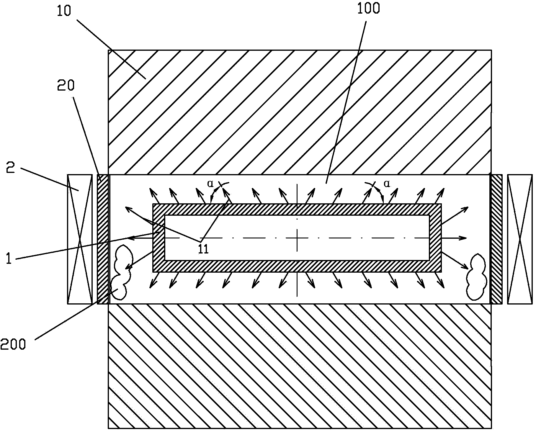
[0036] During the flow distribution process of twin-roll thin strip continuous casting, the pulling speed of the crystallization roll is 50m / min; the liquid level of the molten pool is 200mm; the distance from the upper edge of the discharge hole of the flow distributor to the liquid level is 4mm; The tilt angle is 65°; the electromagnetic intensity of the electromagnetic induction device is 0.09T.

Embodiment 2

[0038] During the flow distribution process of twin-roll thin strip continuous casting, the pulling speed of the crystallization roll is 70m / min; the liquid level of the molten pool is 220mm; the distance from the upper edge of the discharge hole of the flow distributor to the liquid level is 6mm; The inclination angle is 50°; the electromagnetic intensity of the electromagnetic induction device is 0.11T.

Embodiment 3

[0040] During the flow distribution process of twin-roll thin strip continuous casting, the pulling speed of the crystallization roll is 90m / min; the liquid level of the molten pool is 240mm; the distance from the upper edge of the discharge hole of the flow distributor to the liquid level is 7mm; The inclination angle is 40°; the electromagnetic intensity of the electromagnetic induction device is 0.13T.

[0041] Thin strip continuous casting technology is one of the most competitive technologies in the 21st century. It has advantages incomparable to conventional continuous casting in terms of energy saving and environmental protection, so it has attracted great attention from all over the world; There are many defects. Through the inclination of the discharge hole of the distributor and the control of the electromagnetic induction device on the molten steel, the removal of scum during the molten steel casting process is realized. On the one hand, the process is simple and the...


PUM


Abstract

Provided is a thin-strip continuous casting flow distribution scum removing method. In dual-roller thin-strip continuous casting, a flow distributing device is arranged in a liquid steel molten pool composed of two crystallization rollers rotating reversely and side sealing plates, the flow distributing device is of a rectangular box structure, a plurality of discharge holes are symmetrically formed along the periphery of the flow distributing device, and the discharge holes are inclined towards the two sides with the central lines of the four edges of the flow distributing device as benchmarks. Electromagnetic induction devices are arranged on the two sides of the side sealing plates respectively to enable liquid steel in the molten pool to have the tendency of moving towards the center under the electromagnetic effects, and thus slots are formed between the side sealing plates and the liquid steel molten pool close to the side sealing plates. Through the inclined design of the discharge holes of the flow distributing device, the liquid steel can be pushed to move towards the side sealing plates from the center of the molten pool, scum can enter the slots when the scum moves to the liquid steel slots formed near the side sealing plates due to the electromagnetic effects, a part of the scum entering the slots drops from the bottoms of the side sealing plates along with the rotation of the crystallization rollers, and the other part of the scum is attached to the edges of a cast strip due to fluctuation and is separated from the cast strip along with the subsequent edge cutting of the cast strip.

Description

technical field [0001] The invention relates to the field of thin strip continuous casting, in particular to a thin strip continuous casting cloth flow slag removal method. Background technique [0002] Twin-roll strip continuous casting is a growth process in which two casting rolls rotating in opposite directions are used as crystallizers to directly produce liquid metal into thin strip steel with a thickness of less than 10mm. Compared with the traditional thin strip production process, this technology has the advantages of shortening the process flow, saving energy, reducing production costs and improving the mechanical properties of the strip, so this technology is considered to be one of the most promising near net shape continuous casting technologies in the 21st century one. [0003] The thin strip continuous casting process is a casting and rolling process that is both related and different from traditional continuous casting. Such as figure 1 As shown: its main ...

Claims


Application Information

Patent Timeline
Patent Type & Authority Applications(China)
IPC IPC(8): B22D11/06B22D11/115
Inventor 任三兵樊俊飞方园
Owner BAOSHAN IRON & STEEL CO LTD
Why Eureka
Try Eureka