
Combined punching and shearing machine

A technology of punching and shearing machines and scissors, which is applied to other manufacturing equipment/tools, manufacturing tools, etc., can solve problems such as insufficient punching and shearing force, easy to cause pollution, and single function of punching and shearing machines, so as to avoid oil leakage, save energy, The effect of simple structure

Inactive Publication Date: 2014-05-28
SHANGHAI SUQIAO MECHANICAL EQUIP
View PDF0 Cites 0 Cited by
  • Summary
  • Abstract
  • Description
  • Claims
  • Application Information

AI Technical Summary

Problems solved by technology

[0004] The technical problem to be solved by the present invention is: in order to overcome the problems of existing punching and shearing machines such as single function, insufficient punching and shearing force, and easy pollution, a combined punching and shearing machine is provided, which has a simple structure, sufficient shearing force, and high performance. comprehensive

Method used


Image

  • Combined punching and shearing machine

Examples


Embodiment Construction

[0010] The present invention is described in further detail now in conjunction with accompanying drawing. These drawings are all simplified schematic diagrams, which only illustrate the basic structure of the present invention in a schematic manner, so they only show the configurations related to the present invention. After reading the content of the present invention, those skilled in the art can make various modifications to the present invention, and these equivalent changes and modifications also fall within the scope of protection defined by the present invention.

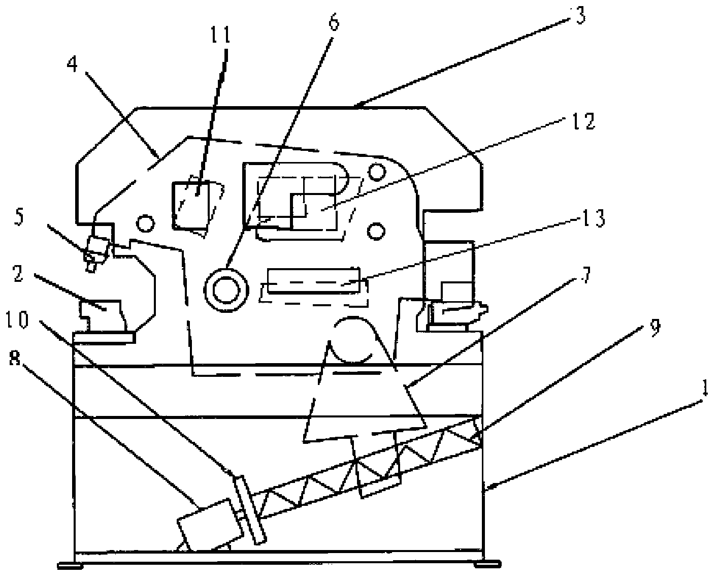
[0011] Such as figure 1 As shown, a combined punching and shearing machine has a machine base 1 and a mold base 2, a scissor frame 3 is installed on the machine base 1, a scissor device 4 is installed on the scissor frame 3, and a punch 5 is provided at the left end of the scissor device 4, The punch 5 corresponds to the position of the die base 2, the scissors device 4 is connected to the scissors frame 3 t...


PUM


Abstract

The invention discloses a combined punching and shearing machine which comprises a base and a die holder. A shear shank is mounted on the base, a shear device is mounted on the shear shank and is connected with the shear shank by a rotation center, a connecting seat is arranged on the lower portion of the shear device and is hinged to the shear device, a motor and a lead screw are arranged in the base, the lead screw is connected with an end of the motor, the connecting seat is connected with the lead screw in a threaded manner, an I-section steel and channel steel shearing device is arranged on the left side of the surface of the shear device, an angle steel shearing device is arranged on the right side of the surface of the shear device, and a flat steel shearing device is arranged on the right lower side of the surface of the shear device. The combined punching and shearing machine has the advantages that the combined punching and shearing machine is simple in structure and is driven by the motor, so that sufficient shearing force can be generated; the combined punching and shearing machine does not need to be driven by a cylinder, so that oil leakage and environmental pollution can be prevented; the combined punching and shearing machine has a multi-station acting function, so that the work efficiency can be improved, the production cost can be reduced, and energy can be saved.

Description

technical field [0001] The invention relates to equipment for shearing steel, in particular to a combined punching and shearing machine. Background technique [0002] The current punching and shearing machines are generally driven by oil cylinders or cylinders. The force driven by the cylinders is not strong enough. When cutting relatively large steel materials, the force is not strong enough to cut cleanly at one time; the drive by oil cylinders is not environmentally friendly, and it is easy to leak oil. The surrounding environment is polluted. [0003] And the structure of punching and shearing machine is complicated, and function is single, and bulky and heavy. Contents of the invention [0004] The technical problem to be solved by the present invention is: in order to overcome the problems of existing punching and shearing machines such as single function, insufficient punching and shearing force, and easy pollution, a combined punching and shearing machine is provi...

Claims


Application Information

Patent Timeline
Patent Type & Authority Applications(China)
IPC IPC(8): B23P23/00
CPCB23P23/04
Inventor 黄正华
Owner SHANGHAI SUQIAO MECHANICAL EQUIP
Learn More