
Wireless measurement system for debugging power transmission lines

A technology of wireless measurement and transmission lines, applied in the direction of measuring electricity, using digital measurement technology for measurement, and measuring devices, etc., can solve problems such as increasing work intensity, reducing work efficiency, and high overvoltage, so as to improve work efficiency and avoid Effect of wiring work and ensuring personal safety

Active Publication Date: 2014-05-28
STATE GRID CORP OF CHINA +2
View PDF4 Cites 10 Cited by
  • Summary
  • Abstract
  • Description
  • Claims
  • Application Information

AI Technical Summary

Problems solved by technology

This measurement method is extremely cumbersome. In some large substations, the cable length can reach nearly 100 meters. The workload of field wiring is heavy, which consumes a lot of time and energy of testers, reduces work efficiency and increases work intensity.
Due to the complex electromagnetic environment of the substation, a high overvoltage may be induced in the cable, which affects the safe and reliable operation of the measurement system
During the test, the cable may be pulled or crushed to cause circuit breakage, which poses a great risk

Method used


Image

  • Wireless measurement system for debugging power transmission lines
  • Wireless measurement system for debugging power transmission lines
  • Wireless measurement system for debugging power transmission lines

Examples


Embodiment Construction

[0016] In order to make the technical means, creative features, goals and effects achieved by the present invention easy to understand, the present invention will be further described below in conjunction with specific embodiments.

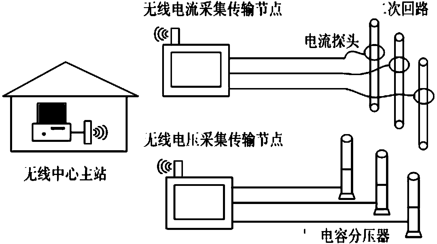
[0017] see figure 1 , A wireless measurement system for power transmission line debugging according to the present invention includes a wireless central master station, a wireless current collection and transmission node, and a wireless voltage collection and transmission node.

[0018] Among them, the main station of the wireless center faces the user and is responsible for controlling the wireless current collection and transmission nodes and wireless voltage collection and transmission nodes, receiving data from wireless current collection and transmission nodes and wireless voltage collection and transmission nodes, and simultaneously performing data storage, waveform display, data analysis, and reporting automatically generated etc.

[0019]...


PUM


Abstract

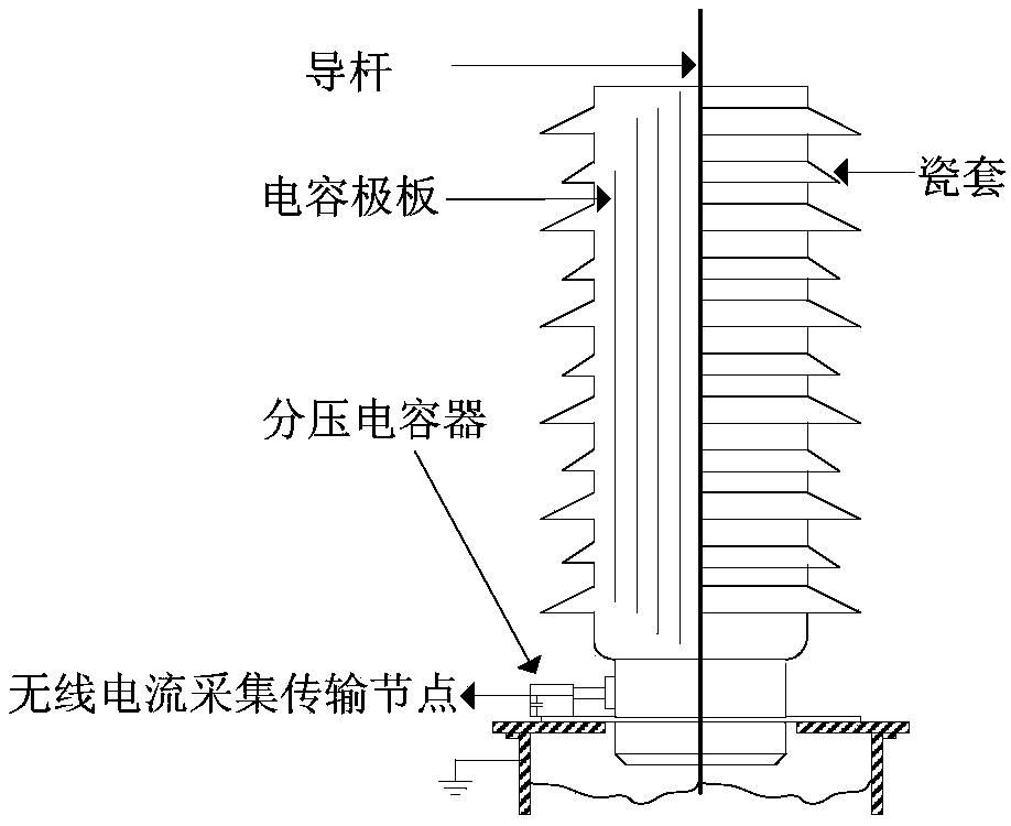
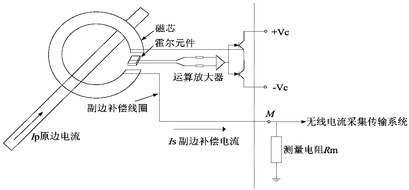
The invention discloses a wireless measurement system for debugging a power transmission lines. The wireless measurement system for debugging power transmission lines comprises a wireless voltage collecting and transmitting node, a wireless current collecting and transmitting node and a wireless center master station, wherein the wireless voltage collecting and transmitting node is connected with a low voltage side of a capacitive voltage divider of an outdoor field of a transformer substation, and is used for collecting a voltage signal of the low voltage side of the capacitive voltage divider; the wireless current collecting and transmitting node is connected with a hall current sensor installed on the secondary side of a current transformer, and is used for collecting a current signal of a hall current sensor; the wireless center master station comprises a center master station wireless communication module, a server and a client; the server is connected with a wireless communication module of the center master station; data collected by the wireless current collecting and transmitting node and the wireless current collecting and transmitting node are uploaded to the wireless center master station in real time. The wireless measurement system for debugging power transmission lines, which is provided by the invention, can prevent the complex wiring operation of a wireless circuit debugging field, reduces the working intensity greatly, improves the working efficiency, and can guarantee weak current equipment of a measurement system and personal safety of measurement workers.

Description

technical field [0001] The invention relates to a wireless measurement system, in particular to a wireless measurement system for debugging a power transmission line. Background technique [0002] Before the new high-voltage transmission line is put into operation, in order to assess the insulation performance of the line, the circuit breaker will be opened and closed continuously at the head end of the line to simulate the electromagnetic transient process of the system. During the test, the voltage and current signals of the transmission line are measured to reflect the insulation status of the line. [0003] The existing measurement system usually consists of capacitive voltage divider, current transformer, photoelectric isolator, wave recorder and so on. In order to ensure the personal safety of the measuring personnel during the test and to supply power to the measuring instruments, photoelectric isolators, wave recorders and other equipment are usually arranged indoor...

Claims


Application Information

Patent Timeline
Patent Type & Authority Applications(China)
IPC IPC(8): G01R19/25G01R31/00
Inventor 孙秋芹马勇颜彪陶风波刘洋周志成
Owner STATE GRID CORP OF CHINA
Learn More