

Touch and motion detection using surface map, object shadow and a single camera
A technology for mapping graphs and objects, applied in the field of methods and systems, to solve problems such as the inability to obtain a unique solution
- Summary
- Abstract
- Description
- Claims
- Application Information
AI Technical Summary
Problems solved by technology
Method used
Image

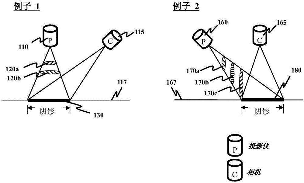
Examples
Embodiment Construction
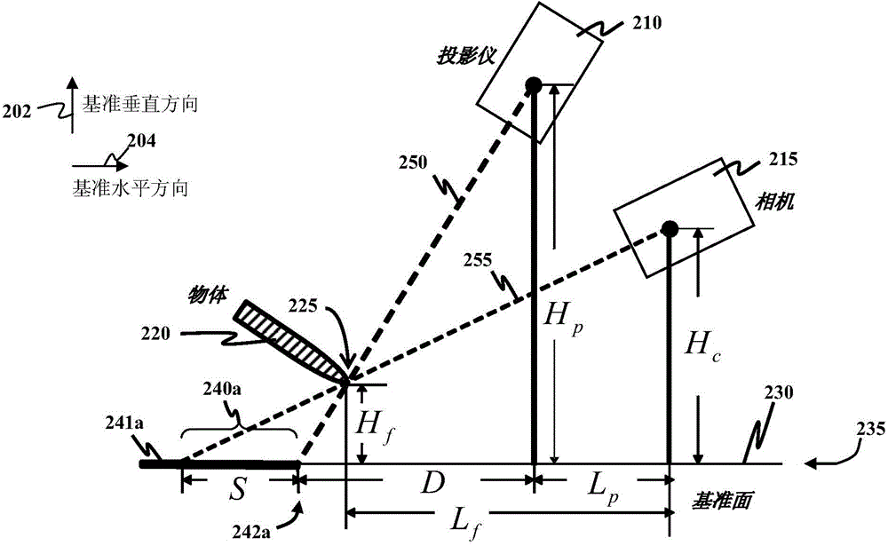
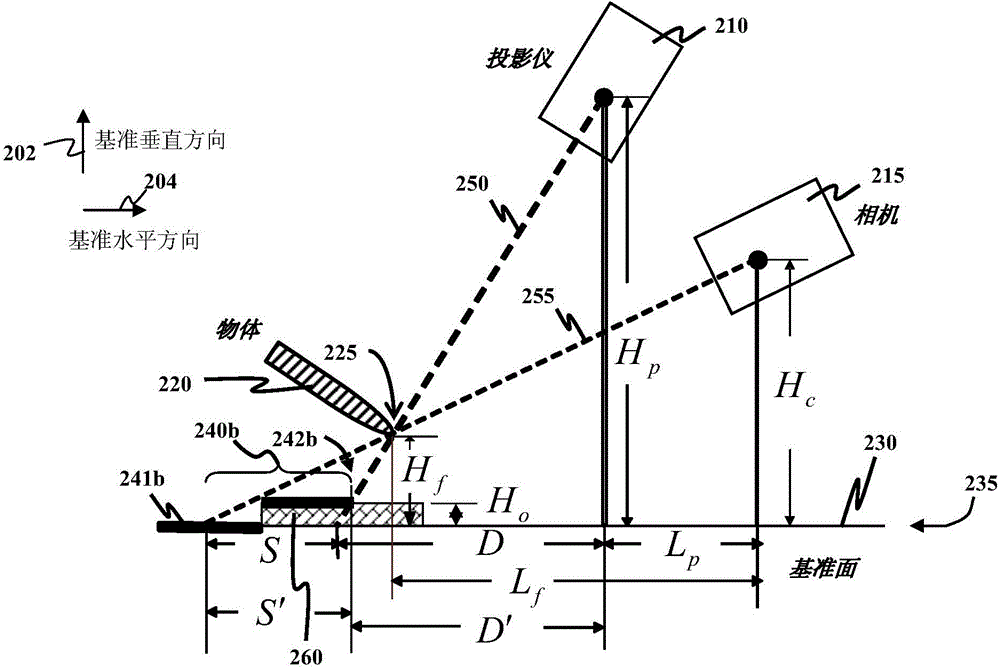
[0028] As used herein, "a reference vertical direction" and "a reference horizontal direction" are defined as two mutually perpendicular and orthogonal directions, but these two directions are not defined with respect to the direction of gravity. Assuming that the reference plane is flat, a reference vertical direction is defined as a direction perpendicular to said reference plane, and a reference horizontal direction is defined relative to said reference vertical direction. For example, the reference plane can be a floor surface or a wall. If the datum is not flat, an imaginary plane representing the datum is used instead of the original datum to define the datum vertical. That is, if the reference plane is not flat, the reference vertical direction is defined at this time as the direction perpendicular to the imaginary plane.
[0029] As used in this specification and the appended claims, the "height of an object above a reference plane" is defined as the distance from a p...
PUM
 Abstract
Description
Claims
Application Information