Methods And Systems For Predictive Torch Height Control

a technology of height control and prediction method, applied in the field of part cutting technology, can solve the problems of ineffective interference between sensitive electronics in sensors used in different measurement systems, high risk of cutting head colliding with the plate in the field of part cutting, and high risk of large cutting distance,

Active Publication Date: 2009-12-17
FAGAN MATTHEW
View PDF16 Cites 46 Cited by
  • Summary
  • Abstract
  • Description
  • Claims
  • Application Information

AI Technical Summary

Benefits of technology

[0061]While a significant advantage of various embodiments of the present systems and methods is the accurate prediction of plate height and improvement of torch height control during cutting, other advantages include the automatic determination of the plate shape and the effective elimination of problems associated with torch dives and cut quality for holes and corners. A still further advantage of various embodiments of the present system and methods is the continuing independence from the NC program itself, in that no change to the NC program is required to predict / obtain very accurate torch height values at all points on the plate. Therefore, the present systems and methods may result in better cut quality even for traditional vertical cutting, as a replacement for current torch height control feedback systems. The requirement to turn height control on and off during cutting also becomes unnecessary, and no modifications to the NC program, or extensions to the NC language, are required. Presently known programming languages, such as ESSI, can immediately utilize the present systems and methods without additional changes.

Problems solved by technology

The risk of the cutting head colliding with the plate is much too high in practice for large parts and long distance cuts.
AVC systems are convenient for plasma arc cutting because interference between sensitive electronics in a sensor used in a different measurement system, in the presence of a plasma arc, might be rendered ineffective.
Mechanical devices that physically contact the plate for cutting are generally more accurate than AVC devices, but mechanical devices are known to experience problems when their cutting heads run over previously cut paths, or fall into holes in the workpiece.
Such difficulties can require very complex NC programs to avoid these obstacles to efficient cutting.
Ball bearing mechanical feet, for example, can become clogged with dirt or metal from the surface of or waste from the workpiece.
AVC is also known to be less useful for cutting small holes and tight corners, because the typical fluctuations in arc conditions can produce unfavorable torch height changes, thereby resulting in lower quality cuts.
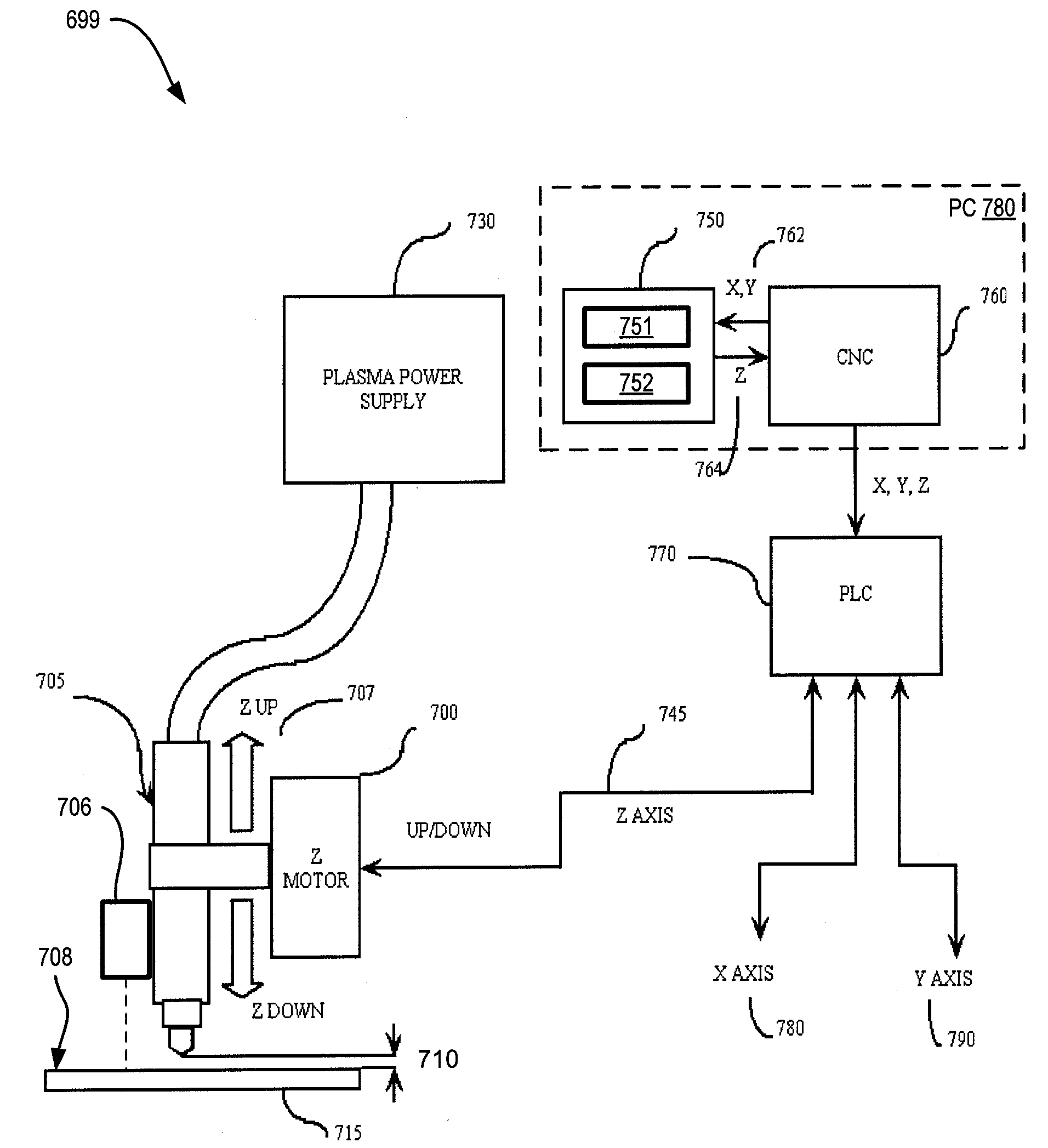
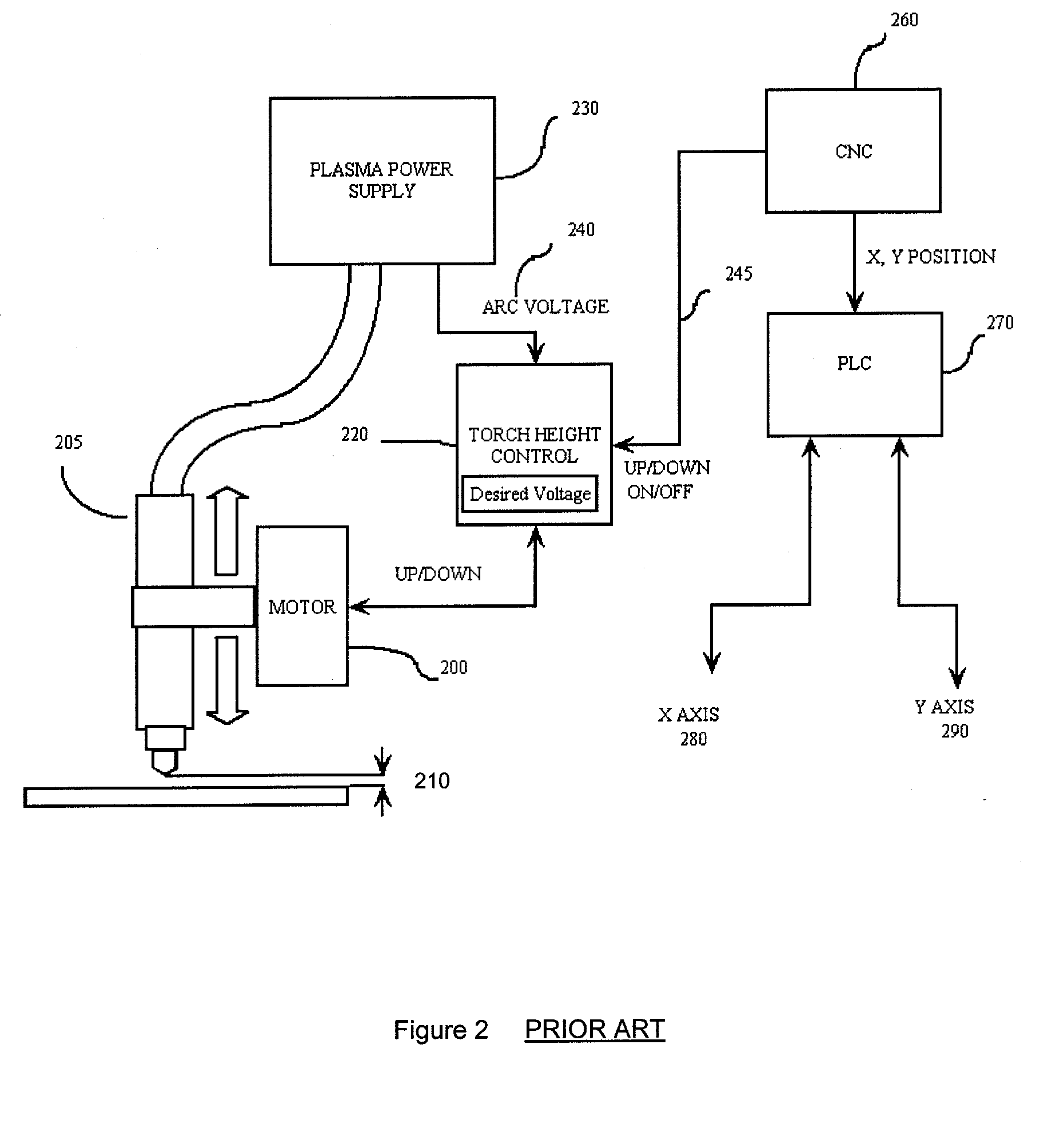
One significant drawback to using conventional feedback THC systems, such as that shown in FIG. 2, is that when torch 205 traverses a hole in the material, torch 205 can “dive” (i.e., drop into the hole).
The dive results from the THC system are unable to distinguish between the hole versus a simple variation in the height of the material of the workpiece.
Torch dives can result in poor quality cutting, and also in damaging collisions between the torch and the workpiece material.
Torch dives are difficult to avoid because the cutting path of a part will invariably encounter a hole at least near the exit from the cutting path to drop the cut part from the workpiece material.
Similarly, a void in the workpiece can also be encountered in the cutting path when a piece of adjacent scrap material may have already fallen out of the workpiece from an earlier cut.
Because torch lifts can slow the cutting process significantly, full torch lifts for each part or hole can add greatly to the time needed to cut and process a nest of parts, or to traverse a pattern of holes in one part.
Beveling is of great commercial interest because most cut materials have to be subsequently welded to other parts, which in the art is typically a slow, difficult, messy, and expensive manual process.
In edge beveling operations, however, the greatest problems are known to occur with independent THC systems that are based on continual feedback from height sensors while cutting.
Accordingly, conventional beveling machines experience unplanned vertical movement of the torch, i.e., other than for a variation of torch-to-plate distance 210 (see FIG. 2), resulting in incorrect cuts of the outline of respective parts.
These factors are not considered to cause problems for vertical cutting applications, but will certainly lead to significant accuracy problems in bevel cutting, as point 330 is not the desired point 320.
If, however, the THC varies within the typical ±3 mm, as discussed above, such tolerances are impossible to achieve.
Because of such difficulties in achieving desired dimension tolerances for beveled parts, the use of NC flame, waterjet, and plasma machines for preparation of weld-ready parts has been historically unacceptable.
Attempts with such machines to do any cutting other than vertical are often abandoned.
The largest manufacturers of such machines have attempted to produce multi-pass bevel machines for many years, but most have abandoned AVC based systems as unworkable.
However, in practice, limiting the cuts to only short distances and / or small workpieces is not practical or economically feasible.
A typical programmer is not generally considered capable of programming the NC machine to perform within required tolerances.
The coding of the NC program must also be completed before nesting occurs, which factor is a significant impediment to the nesting process itself.
While the Messer Greisham approach can be better than the dynamic feedback approach in beveling operations, because the Z height is theoretically “correct” at the start of each machine movement, a problem still occurs where the approach of the torch is based on the assumption that Z varies linearly between the points that are actually measured in advance of the cutting operation.
As discussed above, many factors can drastically reduce the feasibility of such an assumption.
Accordingly, the Messer Greisham approach can create dangerous risks to the machine parts, since distance between the workpiece and the cutting head, for example, is not a straight line over the entire cutting, thereby resulting in a significant risk of a collision between plate and torch.
The Messer Greisham approach further requires the use of special codes in the NC program, which makes the programming nonstandard, thereby requiring additional extensions to most standard NC languages, especially to the ESSI code discussed above, as well as additional costs and resources to implement the approach effectively.

Method used


Image

  • Methods And Systems For Predictive Torch Height Control
  • Methods And Systems For Predictive Torch Height Control
  • Methods And Systems For Predictive Torch Height Control

Examples


Embodiment Construction

[0041]FIG. 7 shows one exemplary predictive torch height control system for a numerical control (NC) machine 699 that cuts parts out of a plate 715. Plate 715 may also be referred to as a workpiece, hereinafter. NC machine 699 includes a computer numerical controller (CNC) 760, a programmable logic controller (PLC) 770, a Z axis motor 700 and a plasma cutting torch 705 powered from a plasma power supply 730. Although shown as a plasma cutting torch and supply in this example, cutting torch 705 and plasma power supply 730 may represent any type of cutting torch known in the art. As shown, CNC 760 sends X, Y and Z coordinates to PLC 770, which in turn outputs X axis 780 and Y axis 790 values to control horizontal position of cutting torch 705 (i.e., control of a gantry carrying cutting torch 705) and outputs Z axis value 745 to Z axis motor 700 for controlling a vertical movement 707 of cutting torch 705.

[0042]NC machine 699 also includes a surface prediction module 750 that interface...


PUM

PropertyMeasurementUnit
thicknessaaaaaaaaaa
thicknessaaaaaaaaaa
thicknessaaaaaaaaaa

Abstract

A method for controlling a height of a cutting torch, includes loading a workpiece onto a numerical control machine, scanning the workpiece with a scanning device at a plurality of discrete points on an upper surface of the workpiece, measuring an X-, a Y-, and a Z-coordinate for each respective one of the scanned discrete points, where X and Y define a plane substantially parallel to the loaded workpiece and Z represents a distance between the upper surface and the scanning device at a respective discrete point, storing the measured XYZ coordinates from each of the scanned discrete points into a data set, mathematically fitting the stored data set to a smooth surface representative of the upper surface of the loaded workpiece, and cutting the workpiece along a cutting path programmed into the numerical control machine, while controlling the cutting torch height to correspond to the representative smooth surface.

Description

CROSS-REFERENCE TO RELATED APPLICATIONS[0001]This application is related to and claims the benefit of pending U.S. Provisional Patent Application No. 61 / 073,323, filed on Jun. 17, 2008, and entitled “Method And System For Predictive Torch Height Control”, the entire contents of which are incorporated herein by reference.FIELD OF THE INVENTION[0002]The present application relates to the field of part-cutting technology, and more particularly to the field of cutting parts from metal sheets or plates by controlling cutting torch height. The present application can be applied to cutting of flat metal plates and sheets, and also to control beveling systems where torches cut at an angle other than vertical to a part's surface.BACKGROUND OF THE INVENTION[0003]Referring to FIG. 1, a Numerical Control machine, or NC machine, is a cutting machine with a numerical control unit 150 that guides a path of a cutting tool (e.g., a cutting torch 125), above a bed 140 on which a generally flat sheet ...

Claims


Application Information

Patent Timeline
Patent Type & Authority Applications(United States)
IPC IPC(8): G05B19/19
CPCB23K10/006B23K26/38B23K26/048B23K26/046
Inventor FAGAN, MATTHEW
Owner FAGAN MATTHEW
Why Eureka
Try Eureka