System and method for 3D radar image rendering

a technology of radar image and system, applied in the field of radar imaging methods, can solve the problems of not being able to detect objects with vertical dimensions not stored in the database, not providing all three coordinate dimensions in the conventional radar imaging system, and not being able to provide the proper height of objects in the image, etc., to enhance depth perception and ridgeline detection, enhance image quality, and enhance usability.

Active Publication Date: 2008-03-27
SIERRA NEVADA CORP
View PDF3 Cites 53 Cited by
  • Summary
  • Abstract
  • Description
  • Claims
  • Application Information

AI Technical Summary

Benefits of technology

[0012]The aforementioned need in the art is addressed by a novel three-dimensional (3D) radar image rendering system and method in accordance with the present invention. (Rendering is the process of generating an image from a model, by means of a software program. In the present application, the model is the description of three-dimensional objects, while the generated image is displayed on 2D computer graphics terminal). The invention provides significant improvement in the usability of airborne radar imaging systems. The illustrated embodiment optimally blends the data acquisition method and rendering techniques to provide pilot-centered, easily interpretable radar images.
[0015]In some applications, it may be desired to weight the triangle color or shading based on the distance from a desired perspective, thereby to enhance depth perception and ridgeline detection. A commercially available software package is then used to transform the 3D surface to the desired perspective (e.g., the pilot's seat, looking in the direction of the fuselage reference line).
[0016]The data acquisition relies on real time scanning and measurement of the terrain to get accurate information of the topology. This scanning and measurement technique combines radar and navigational data to locate and map vertical obstacles in the target area. The employed graphic animation process allows the presenting of the reconstructed image from a desired perspective, which, in the most cases, is the pilot's perspective. Viewing a terrain from the pilot's perspective allows the easiest interpretation of the presented images. The rendering technique employed by the system further enhances usability of the system by providing life-like 3D images. The enhanced image quality is partially derived from more detailed and accurate vertical information. The result is a more natural image, thereby facilitating human interpretation.

Problems solved by technology

Conventional radar imaging systems do not provide all three coordinate dimensions (there is no elevation angle measurement) of the location of the basic resolution cell to enable the transformation of data (i.e., the image) to another perspective.
Thus, they do not present objects at the proper height in the image, from the pilot's perspective.
This approach suffers primarily in two respects: First, there is no capability of detecting objects with a vertical dimension not stored in the database, such as construction towers erected since the database was last updated.
Second, the required resolution for some applications is not available, such as is the case when a helicopter is landing in a dust cloud or fog, where a resolution on the order of one foot (30 cm) is required to assure the pilot's situational awareness.
Since the human eye is accustomed to receiving both radiated and reflected energy from detected surfaces, the reconstructed radar image seems unnatural.
The current state of the art in radar imaging is unable to provide angular resolution comparable with EO / IR sensors.
This lack of resolution causes a very grainy image in the azimuth dimension which, when coupled with the specular reflection characteristics, makes human interpretation of most radar images difficult.

Method used


Image

  • System and method for 3D radar image rendering
  • System and method for 3D radar image rendering
  • System and method for 3D radar image rendering

Examples


Embodiment Construction

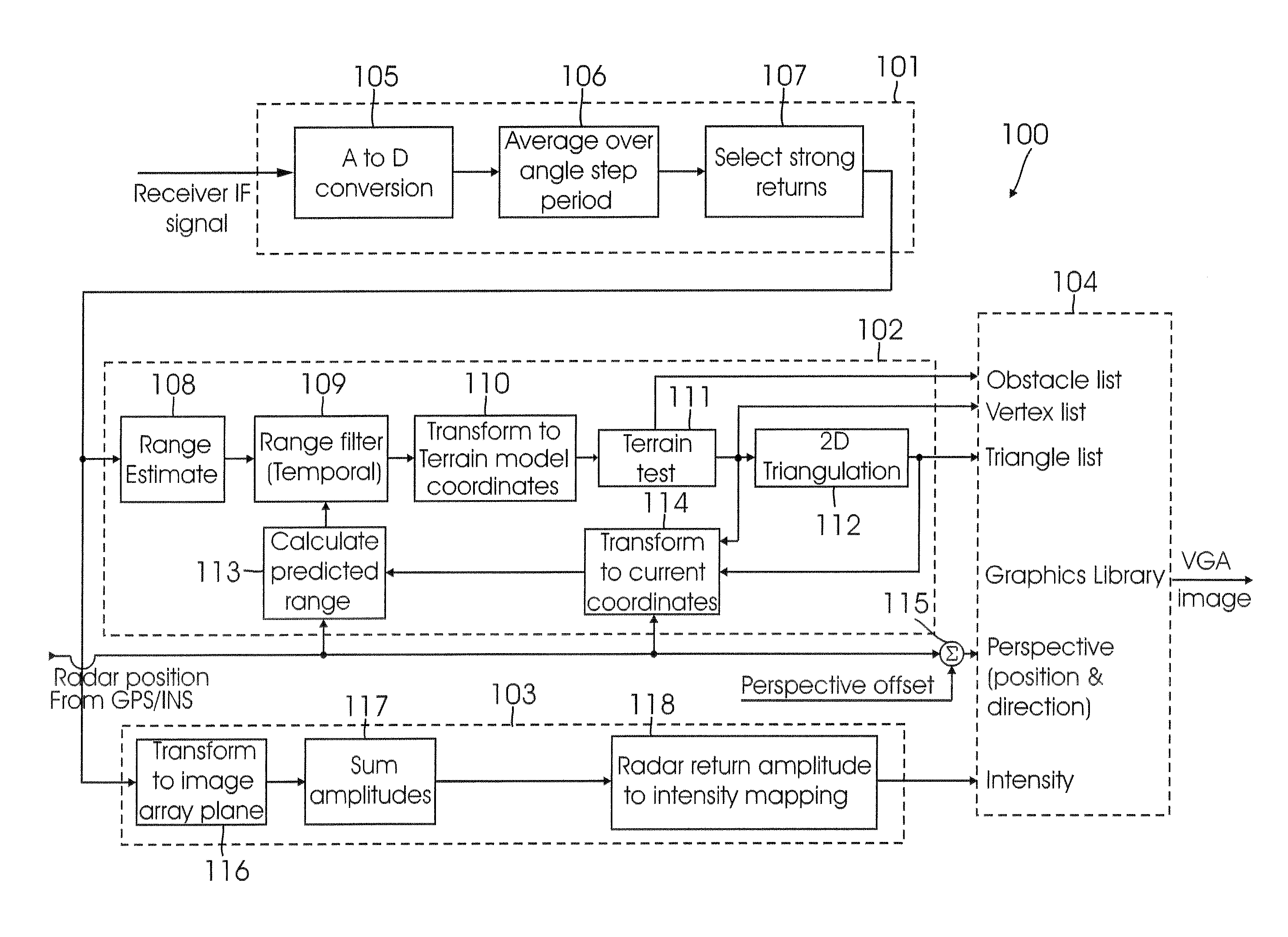
[0027]The radar imaging system described herein employs a three-dimensional (3D) radar scan having range, azimuth, and elevation data components. Data are obtained by direct measurement of a location of a surface cell, range of return for each step in the angle scan, and amplitude of the return from the cell. The availability of all three dimensions for each point allows the transforming of all data into a Cartesian frame (X, Y horizontal plane coordinates, Z vertical coordinate). The X, Y coordinates of all cells causing returns are connected by lines to form triangles, thereby creating a 3D “mesh” of triangles (using prior art techniques) that describe the detected surface, as shown in FIGS. 5-7.

[0028]As described above briefly, the detected surface model comprises an arrangement or “mesh” of contiguous triangular areas, the edges of which are straight lines. By using straight lines on the display device to connect the vertices of the triangles for which the position uncertainty i...


PUM


Abstract

A 3D rendered image of a radar-scanned terrain surface is provided from a radar return signal from the surface, wherein the return signal includes data indicative of azimuth, elevation, and range of a radar-illuminated area of the surface. The data are processed for transformation into X, Y, and Z coordinates. The X and Y coordinates corresponding to each illuminated area are triangulated so as to create a mesh of triangles representing the terrain surface, each of the triangles in the mesh being defined by a vertex triplet. 3D imaging information (grey scale shading and / or coloring information) is added to each triangle in the mesh, based on the amplitude of the radar return signal from the coordinates represented by each vertex in the triplet and the value of the Z coordinate at each vertex, so as to form the 3D rendered image.

Description

CROSS-REFERENCE TO RELATED APPLICATIONS[0001]Not ApplicableFEDERALLY SPONSORED RESEARCH AND DEVELOPMENT[0002]Not ApplicableBACKGROUND OF THE INVENTION[0003]The present invention relates to the field of radar imaging methods. More specifically, the present invention relates to a system and method for radar image rendering.[0004]Enhanced vision systems are vital in the control of aircraft, especially during take off approach, and landing in adverse conditions. Radar and Electro-Optical Infra-Red (EO / IR) systems are frequently relied upon to provide these capabilities. The effectiveness of these systems greatly depends on the quality of their imaging technology.[0005]Imaging techniques are well known and widely used in the art. Certain imaging technologies are better suited for certain applications. For example, radar imagery is widely used for navigation, surveillance, and reconnaissance, as well as target tracking and identification.[0006]Radar imagery is conventionally accomplished ...

Claims


Application Information

Patent Timeline
Patent Type & Authority Applications(United States)
IPC IPC(8): G01S13/90G01S13/89G01S13/935G06T15/10
CPCG01S7/20G01S13/89G06T17/05G06T15/10G01S13/94G01S13/935
Inventor CROSS, JACKBOSWORTH, THEODORECHAPMAN, CRAIGHOWARD, DAVID
Owner SIERRA NEVADA CORP
Why Eureka
Try Eureka