
Electronic system, power amplifier and temperature compensation method of power amplifier

A power amplifier, voltage compensation technology, applied in power amplifiers, improving amplifiers to reduce temperature/power supply voltage changes, etc., can solve the problems of output current and output power drop, power amplifier linearity attenuation, amplified signal distortion, etc. Temperature compensation effect, high linearity effect

Active Publication Date: 2014-05-28
UNIVERSAL SCIENTIFIC INDUSTRIAL (SHANGHAI) CO LTD +1
View PDF2 Cites 7 Cited by
  • Summary
  • Abstract
  • Description
  • Claims
  • Application Information

AI Technical Summary

Problems solved by technology

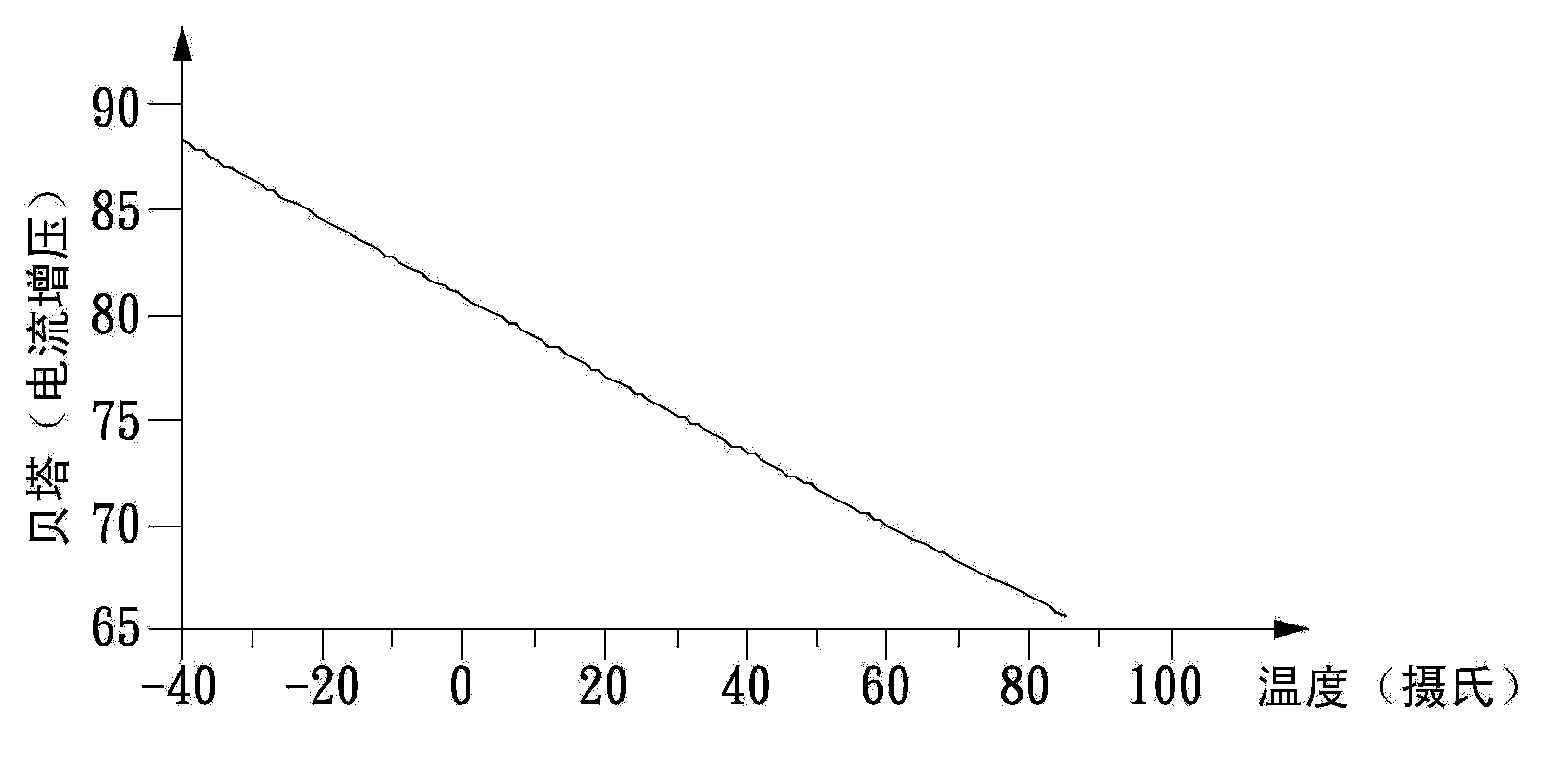
[0002] In the prior art, the bandgap reference circuit is used as the bias circuit in the power amplifier, although it can provide a reference voltage with a temperature coefficient close to zero, but because the power amplifier transistor in the power amplifier is a bipolar junction transistor, The voltage (VBE) and current gain (Beta) between the base and emitter have negative temperature coefficient characteristics, so VBE and current gain (Beta) will decrease gradually with the rise of temperature, which may cause the output current and output The problem of power drop, so there is a hidden worry that the linearity of the power amplifier will be attenuated and the amplified signal will be distorted.

Method used


Image

  • Electronic system, power amplifier and temperature compensation method of power amplifier
  • Electronic system, power amplifier and temperature compensation method of power amplifier
  • Electronic system, power amplifier and temperature compensation method of power amplifier

Examples


Embodiment Construction

[0059] While various exemplary embodiments will be described below with reference to the drawings, inventive concepts may be embodied in many different forms and should not be construed as limited to the exemplary embodiments set forth herein. It should be understood that although the terms first, second, third, etc. may be used herein to describe various elements, these elements should not be limited by these various terms, which are used to distinguish one element from another. Thus, a first element discussed below could be termed a second element without departing from the teachings of the inventive concepts.

[0060] [Example of Power Amplifier]

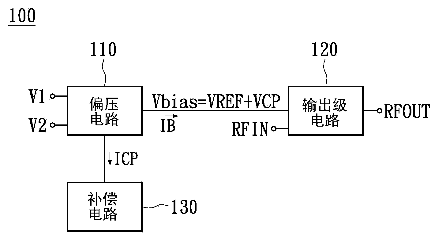
[0061] Please refer to figure 1 , figure 1 It is a schematic block diagram of a power amplifier according to an embodiment of the present invention. Such as figure 1As shown, the power amplifier 100 includes a bias circuit 110 , an output stage circuit 120 and a compensation circuit 130 . The output stage circuit 120 is elec...


PUM


Abstract

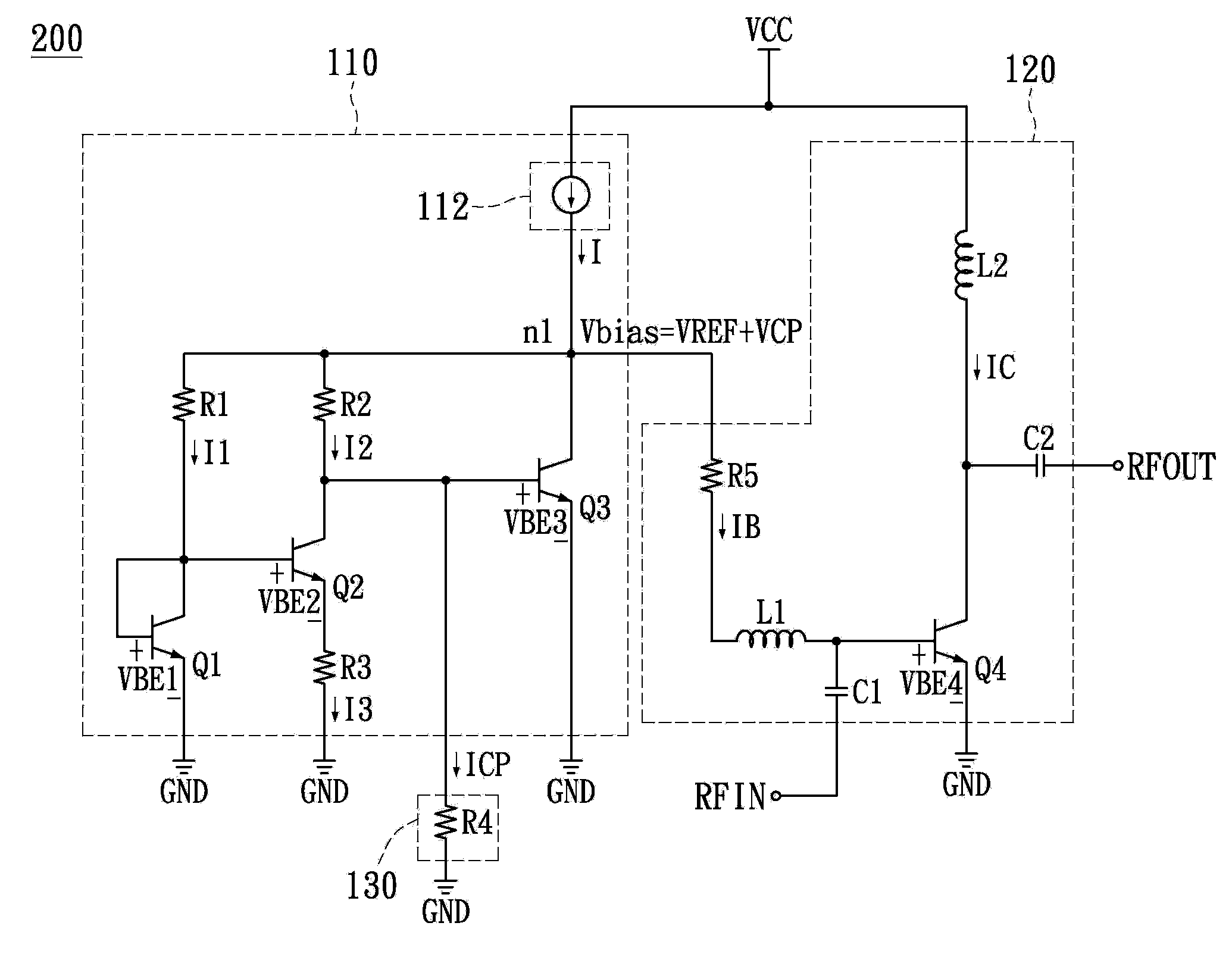
The invention discloses an electronic system, a power amplifier and a temperature compensation method of the power amplifier. The power amplifier comprises a bias circuit, an output stage circuit and a compensation circuit. The bias circuit is used for providing reference voltage. The reference voltage is the sum of first voltage with positive temperature coefficient and second voltage with negative temperature coefficient. The output stage circuit receives working voltage. The compensation circuit receives compensation current, with the negative temperature coefficient, transmitted by the bias circuit and provides compensation voltage with the negative temperature coefficient to the output stage circuit through the bias circuit. The working voltage is the sum of the reference voltage and the compensation voltage. The power amplifier stabilizes the input current of the output stage circuit through the compensation circuit or stabilizes the output current by adjusting the input current into the positive temperature coefficient when the ratio constant between the output current and the input current of the output stage circuit is the negative temperature coefficient.

Description

technical field [0001] The present invention relates to a power amplifier, and more particularly to a power amplifier with temperature compensation. Background technique [0002] In the prior art, the bandgap reference circuit is used as the bias circuit in the power amplifier, although it can provide a reference voltage with a temperature coefficient close to zero, but because the power amplifier transistor in the power amplifier is a bipolar junction transistor, The voltage (VBE) and current gain (Beta) between the base and emitter have negative temperature coefficient characteristics, so VBE and current gain (Beta) will decrease gradually with the rise of temperature, which may cause the output current and output Because of the problem of power drop, there is a hidden worry that the linearity of the power amplifier will be attenuated and the amplified signal will be distorted. Contents of the invention [0003] The object of the present invention is to provide a power ...

Claims


Application Information

Patent Timeline
Patent Type & Authority Applications(China)
IPC IPC(8): H03F1/30H03F3/20
Inventor 丁兆明李威弦温煌华
Owner UNIVERSAL SCIENTIFIC INDUSTRIAL (SHANGHAI) CO LTD
Learn More