A kind of installation method of catalyst module in scr denitrification reactor

A catalyst module and denitrification reactor technology, applied in the field of environmental protection, can solve the problems of inability to set up horizontal supports, large steel consumption, unreasonable structure, etc., and achieve the effects of optimizing the body design, saving cost, and reasonable design

Inactive Publication Date: 2015-09-09
BEIJING BREEZEWIND ENVIRONMENTAL PROTECTION TECH
View PDF3 Cites 0 Cited by
  • Summary
  • Abstract
  • Description
  • Claims
  • Application Information

AI Technical Summary

Problems solved by technology

For the first hoisting method mentioned above, due to the "catalyst trolley track", the upper flange of the steel beam on this layer cannot be supported horizontally, which affects the stability of the catalyst module supporting steel beam on this layer. Therefore, the supporting steel beam of the catalyst module in the conventional reactor All beams need to be box-shaped beams to solve the stability problem, and the minimum height of the catalyst module support beams on this layer also needs to be 600mm
This has brought a lot of "trouble" and constraints to the design of the reactor body structure, resulting in a large amount of steel consumption in the design of the reactor body, and the structure is not very reasonable; although the second solution does not affect the layout of each layer of horizontal support in the reactor, but every installation To complete a row of catalyst modules, it is necessary to dismantle a section of "temporary" double-track track set on the "floor" of this floor, and install a whole floor of catalyst modules. It is necessary to dismantle and assemble the monorail crane that moves vertically on the top of this floor many times, and the installation is laborious and laborious. ,low efficiency
[0007] In view of the installation mode of these two conventional catalysts in engineering, due to the problem of the "catalyst trolley" track, it brings a lot of troubles in design and construction

Method used


Image

  • A kind of installation method of catalyst module in scr denitrification reactor
  • A kind of installation method of catalyst module in scr denitrification reactor
  • A kind of installation method of catalyst module in scr denitrification reactor

Examples


Embodiment Construction

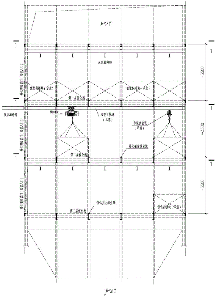
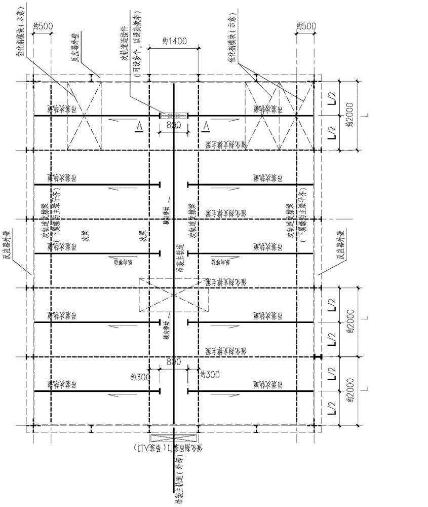
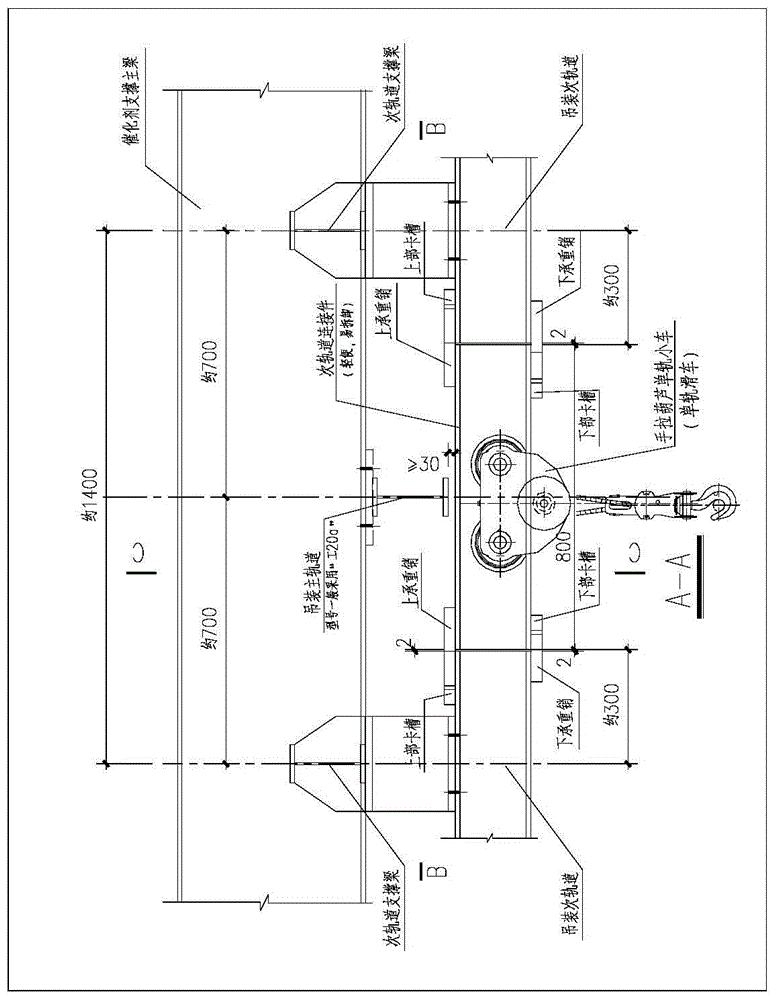
[0023] See figure 1 , figure 2 , Figure 3a , Figure 3b , Figure 3c , the installation method of catalyst module in a kind of SCR denitrification reactor of the present invention, its concrete steps are as follows:

[0024] Step 1, when installing the catalyst module of this layer, set the horizontal "main rail for hoisting" and the vertical "secondary rail for hoisting" at the bottom of the steel beam on the top surface of this layer (that is, the bottom of the steel beam supporting the catalyst module on the previous layer). The catalyst module enters the reactor through "lateral movement" of an electric or manual hoist on the "hoisting main rail". See accompanying drawing of the present invention " figure 1 "--" Schematic diagram of the elevation of the catalyst module in the SCR denitrification reactor." figure 1 " is the installation mode for installing one layer of catalyst. The installation of catalyst modules of other layers shall be carried out according to t...


PUM


Abstract

The invention discloses an assembly method for catalyst modules in a novel SCR (Selective Catalytic Reduction) denitration reactor. The method comprises the following four steps: step one, arranging a transverse hoisting main rail and a vertical hoisting secondary rail on a monorail hoist which is located on the bottom of a top steel beam of a layer when assembling the catalyst modules of the layer, and enabling the catalyst modules to enter a reactor along with transverse movement of a manual hoist or an electric hoist which is arranged on the hoisting main rail; step two, putting the catalyst modules down near the hoisting secondary rail after reaching main units through the hoisting main rail, then withdrawing from the electric hoist or manual hoist of the main rail; step three, manually assembling a secondary rail connection part, vertically moving the secondary rail connection part and a manual hoist to hoist the catalyst modules in determined positions; and step four, taking the secondary rail connection part down after a whole line of catalyst modules is assembled for each time and applying the secondary rail connection part to assembly of other lines or other layers. The assembly method for the catalyst modules in the novel SCR denitration reactor is a catalyst module assembling technique which is simple, reliable, easy to operate and convenient to assembly in site.

Description

technical field [0001] The invention relates to a method for installing a catalyst module in an SCR denitrification reactor in the field of environmental protection. It is an improvement on the catalyst module installation technology of the denitrification reactor with imported technology from abroad. The invention belongs to the selective catalytic reduction (SCR) flue gas denitrification technology in the field of environmental protection technology. Background technique [0002] At present, the Selective Catalytic Reduction (SCR) flue gas denitrification method is widely used in domestic and foreign projects due to its high efficiency and stable performance, and has become the mainstream technology for removing nitrogen oxides from exhaust gas. The SCR denitrification system refers to a reaction device system that reduces the nitrogen oxides in the flue gas to nitrogen and water by injecting ammonia into the flue gas under the action of a catalyst. The main equipment of...

Claims


Application Information

Patent Timeline
Patent Type & Authority Patents(China)
IPC IPC(8): B01D53/88B01D53/90B01D53/56
Inventor 杨小虎姚德康肖海涛王伟徐佩
Owner BEIJING BREEZEWIND ENVIRONMENTAL PROTECTION TECH
Why Eureka
Try Eureka