Dust removal system for plasma cutting machine

A technology of plasma cutting machine and dust removal system, which is applied in the field of dust removal system, can solve the problems of low dust removal efficiency, dust flying, etc., and achieve the effect of high dust removal efficiency and improved dust removal ability

Inactive Publication Date: 2016-04-13
SHANGHAI SHIPYARD
View PDF7 Cites 0 Cited by
  • Summary
  • Abstract
  • Description
  • Claims
  • Application Information

AI Technical Summary

Problems solved by technology

[0004] The technical problem to be solved by the present invention is to provide a dust removal system for a plasma cutting machine with a higher dust removal efficiency in order to overcome the defect that the blower airflow in the prior art tends to cause the dust to fly and thus lower the dust removal efficiency

Method used


Image

  • Dust removal system for plasma cutting machine
  • Dust removal system for plasma cutting machine
  • Dust removal system for plasma cutting machine

Examples


Embodiment 1

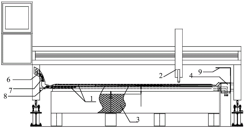
[0030] figure 1 It is the structural representation of the dust removal system of the plasma cutting machine of embodiment 1, as figure 1 As shown, the dust removal system of the plasma cutting machine involved in this embodiment includes an air duct 1 and a cutting device 2 with openings at both ends as a cutting workbench, the air duct 1 is horizontally arranged, and the cutting device 2 is arranged on the air duct 1 Directly above the outlet of the air duct 1 is connected with a suction device 4, and the other end of the air duct 1 is provided with a guide duct.

[0031] The guide pipe includes an axial flow fan interface 6, a soft connection section 7 and an outlet 8. The cross-sectional area of ​​the axial flow fan interface 6 is larger than the outlet 8. The axial flow fan interface 6 is connected to an axial flow fan (not shown in the figure), and the outlet 8 is arranged at one end of several air ducts 1 away from the air suction device 4 .

[0032] There is an inclu...

Embodiment 2

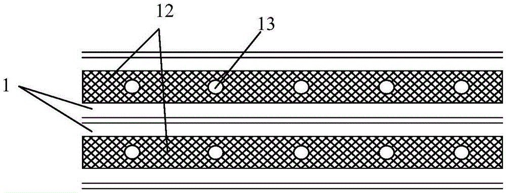
[0046] Embodiment 2 provides a dust removal system for a plasma cutting machine. The difference between Embodiment 2 and Embodiment 1 is that there is no wing-shaped sheet in the air duct of the dust removal system for a plasma cutting machine involved in Embodiment 2. image 3 It is the plan view of the air duct and dust suction duct of embodiment 2, as image 3 As shown, the suction device 4 includes a vacuum generation source (not shown in the figure) and several dust suction pipes 12, and the vacuum generation source communicates with one end of the dust suction pipe 12;

[0047] Several dust suction pipes 12 extend into each air duct 1 respectively, and several dust suction ports 13 are provided directly above the dust suction pipes 12 .

[0048] That is to say, the dust suction duct 12 sucks air upwards in the air duct, and cooperates with the wind blown by the axial flow fan to greatly increase the dust absorption efficiency in each section of the air duct 1 .


PUM


Abstract

The invention discloses a dust removing system of a plasma cutting machine. The dust removing system comprises a plurality of air flues and a cutting device, wherein the two ends of each air flue are respectively provided with an outlet, the air flues are horizontally arranged, the cutting device is arranged over the air flues, the outlet at one end of each air flue is connected with an air suction device, and the other end of each air flue is provided with a flow guide pipeline; the sectional area of the opening at one end of each flow guide pipeline is greater than that of the opening at the other end of the corresponding flow guide pipeline, one end, provided with the large opening, of each flow guide pipeline is provided with an axial flow fan, and the other end of each flow guide pipeline is arranged at one end, far away from the corresponding air suction device, of the corresponding air flue; an included angle ranging from 0 degree to 45 degrees is formed between the end, with the small opening, of each flow guide pipeline and the horizontal plane. Due to the facts that one side of each air flue is provided with the corresponding flow guide pipeline having the included angle with the horizontal plane and the axial flow fans are arranged, dust removing efficiency is higher; dust collection pipelines or wing-shaped slices are arranged inside the air flues, and therefore dust removing ability of the system is further improved.

Description

technical field [0001] The invention relates to a dust removal system, in particular to a dust removal system of a plasma cutting machine. Background technique [0002] At present, plasma cutting machine is widely used as a kind of thermal cutting equipment. Since the working principle of the plasma cutting machine is to use oxygen gas (or air, nitrogen and inert gas) as the working gas of the plasma arc, and use the high-temperature and high-speed plasma arc as the heat source to locally melt the metal to be cut, and at the same time use the high-speed airflow to melt the molten metal. The metal is blown away to form a slit, which will produce a large amount of cutting smoke harmful to the human body during cutting, which greatly exceeds the relevant national standards. Although the plasma cutting machine has a supporting dust removal system, the effect is average, and the dust removal efficiency for the generated smoke and dust is only about 60% to 70%. There is still a ...

Claims


Application Information

Patent Timeline
Patent Type & Authority Patents(China)
IPC IPC(8): B08B15/04B23K10/00
CPCB08B15/007B23K10/00
Inventor 袁家顺张慧华王祈军张雷陆信华吴赛
Owner SHANGHAI SHIPYARD
Why Eureka
Try Eureka