Air inlet position adjusting device

A technology for regulating devices and tuyere, which is applied in grinding/polishing safety devices, metal processing equipment, grinding/polishing equipment, etc., and can solve problems such as accumulation of suction debris, unsatisfactory absorption effect, random flying accumulation, etc.

Inactive Publication Date: 2014-06-04
SIP GOLDWAY TECH
View PDF6 Cites 0 Cited by
  • Summary
  • Abstract
  • Description
  • Claims
  • Application Information

AI Technical Summary

Problems solved by technology

However, some fine chips are bound to be produced during the grinding process. If these fine chips are not treated, they will fly around or accumulate very thick after a long time.
However, in the prior art, a chip suction structure is proposed,

Method used


Image

  • Air inlet position adjusting device
  • Air inlet position adjusting device

Examples


Embodiment Construction

[0020] The present invention will be described in detail below in conjunction with specific embodiments shown in the accompanying drawings. However, these embodiments do not limit the present invention, and any structural, method, or functional changes made by those skilled in the art according to these embodiments are included in the protection scope of the present invention.

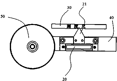
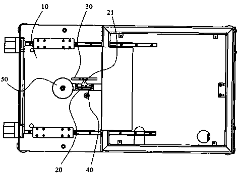
[0021] Please refer to figure 1 with figure 2 As shown, it is a schematic structural diagram of a tuyere position adjustment device of the present invention, including: a workbench 10 for workpiece processing; an air inlet 20 for absorbing fine chips generated during the machining process, which is connected with a vacuum cleaner (not shown) Connection; the scale 30 is located on the surface of the workbench 10 and is located on one side of the air inlet 20, as the adjustment standard of the air inlet device; the pointer 21 is fixed on the side of the air inlet 20 and points to the air inlet 20. The...


PUM


Abstract

The invention discloses an air inlet position adjusting device which comprises a working table used for machining workpieces, an air inlet used for sucking in fines generated during machining, a dividing ruler arranged on the surface of the working table and located on one side of the air inlet, and a pointer which is fixed on the lateral side of the air inlet and points to the dividing ruler, wherein the air inlet is formed in the working table and can move horizontally in the direction opposite to the dividing ruler, and a polisher is arranged at the end, in the horizontally moving direction, of the air inlet. The air inlet position adjusting device is maneuverable, better in fines sucking effect and higher in efficiency.

Description

technical field [0001] The invention relates to the technical field of grinders, in particular to a tuyere position adjusting device for sucking debris at the tuyere of the grinder. Background technique [0002] In the process of mechanical manufacturing, in the connection of workpieces such as welding and riveting, the surface needs to be ground and polished after welding or riveting, so that the surface of the product is round and smooth, and has a good visual sense. However, some fine chips are bound to be produced during the grinding process. If these fine chips are not dealt with, they will fly around or accumulate thickly after a long time. However, in the prior art, a chip suction structure is proposed, and its fixing device is located at a certain corner of the sander. Although it can absorb most of the chip suction, it will still produce a lot of chip suction accumulation in the long run, and the absorption effect will be reduced. Not ideal. [0003] Therefore, it...

Claims


Application Information

Patent Timeline
IPC IPC(8): B24B55/06
CPCB24B55/06
Inventor 李佳
Owner SIP GOLDWAY TECH
Why Eureka
Try Eureka