Wood board drilling equipment
A kind of drilling equipment and wood board technology, applied in the direction of drilling machines, wood processing equipment, manufacturing tools, etc., can solve the problems of inconvenient movement of the cylinder, inconsistent wood size, uneven placement, etc., to achieve the benefit of drilling accuracy and overcome the concave and upturned deformation, reducing labor intensity
- Summary
- Abstract
- Description
- Claims
- Application Information
AI Technical Summary
Problems solved by technology
Method used
Image

Examples
Embodiment 1
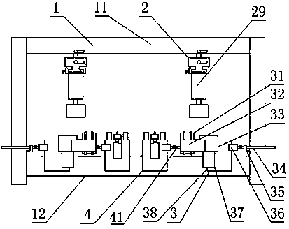
[0030] like Figure 1 to Figure 5As shown, a kind of wood board drilling equipment provided by the present invention includes a frame 1, a pressing part 2 and a drilling part 4 located below the pressing part 2, and both sides of the drilling part 4 are provided with discharging parts 3, The frame 1 includes a beam 11 and a guide rail 12 that are parallel to each other and are located in the horizontal direction. The pressing portion 2 is arranged on the beam 11 and the pressing portion 2 can slide along the length of the beam 11;
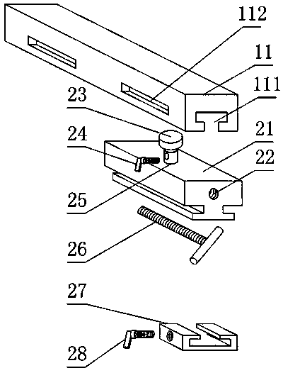
[0031] The pressing part 2 includes a sliding block 21 whose position in the length direction of the beam 11 is adjustable. Below the sliding block 21 is a cylinder mounting table 27 whose position in the length direction of the sliding block 21 is adjustable. cylinder 29;
[0032] The discharge part 3 includes a discharge part base 38 on which a chute is arranged, a discharge motor 37 fixed on the discharge part base 38, a plurality o...
Embodiment 2
[0036] This embodiment makes the following further improvements on the basis of Embodiment 1: as Figure 1 to Figure 5 As shown, in order to facilitate changing the position of the drilled part 4 relative to the frame, the drilled part 4 is provided with a drilled part chute and a drilled part driving mechanism for braking the movement of the drilled part 4 along the guide rail 12 41. Part of the guide rail 12 is located in the chute of the drilled part.
[0037] The drilling portion driving mechanism 41 includes a driving motor and a threaded rod connected to the driving motor. The driving motor is fixedly connected to the drilling portion 4 , and the threaded rod is threadedly connected to the frame 1 . The drilling portion driving mechanism 41 of the above structure is convenient for realizing the accurate positioning of the drilling portion 4 relative to the guide rail 12 and preventing it from moving under unintentional conditions.
[0038] The frame 1 is als...
Embodiment 3
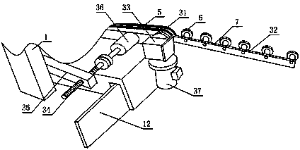
[0040] This embodiment makes the following further improvements on the basis of Embodiment 1: as Figure 1 to Figure 5 As shown, in order to increase the friction force between the material and the discharge part 3 , a conveyor belt 5 is still wound around the discharge brake wheel 31 on each discharge part 3 .
[0041] In order to set the discharge motor 37 as a common motor, a reducer 33 is also connected to the rotor of the discharge motor 37 , and the output stage of the reducer 33 is fixedly connected to any discharge brake wheel 31 .
[0042] In order to facilitate the unloading of the processed materials from the present invention, the unloading part 3 is also provided with a discharge slide rail 32, and the discharge slide rail 32 includes a roller rod 7 and is fixed on the roller rod 7 and extends along the A plurality of rollers 6 distributed in the length direction of the roller stem 7, one end of the roller bar 7 is fixedly connected with the discharge part...
PUM
 Abstract
Description
Claims
Application Information
 - R&D
- Intellectual Property
- Life Sciences
- Materials
- Tech Scout
- Unparalleled Data Quality
- Higher Quality Content
- 60% Fewer Hallucinations
Browse by: Latest US Patents, China's latest patents, Technical Efficacy Thesaurus, Application Domain, Technology Topic, Popular Technical Reports.
© 2025 PatSnap. All rights reserved.Legal|Privacy policy|Modern Slavery Act Transparency Statement|Sitemap|About US| Contact US: help@patsnap.com